36
GV-MFD1501 Series / 2401 Series / 2501 Series / 3401
Series / 5301 Series
1
2
3
4
5
8
9
6
7
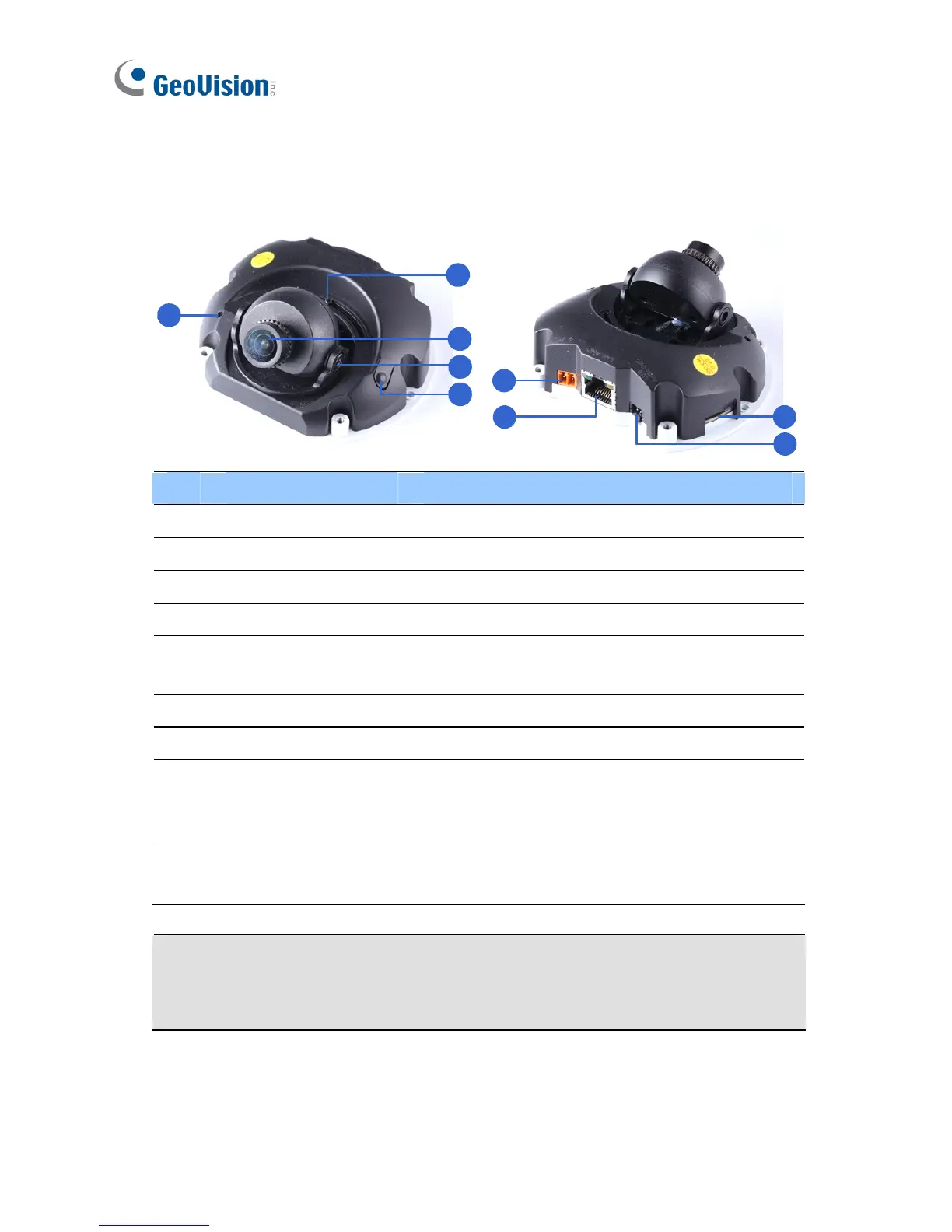
No. Name Description
1 Microphone Receives sound.
2 Pan Screw Loosens the screw to pan.
3 Lens Receives image inputs.
4 Tilt Screw Loosens the screw to adjust tilt angle.
5 Default Button
Resets the camera to default settings. See
27. Restoring to Default Settings.
6 DC 5V Power Port Connects to power.
7 LAN / PoE Connects to a 10/100 Ethernet or PoE.
8 Memory Card Slot
Inserts a micro SD card (SD/SDHC,
version 2.0, Class 10) to store recording
data.
9 USB and Audio Out
Connects to an external hard disk drive and
a speaker through the supplied Y cable.
Note: For details on limitations and requirements of the USB port, refer to
Note for USB Storage and WiFi Adapter at the beginning of the Quick
Guide.
 Loading...