EasyManuals Logo

GeoVision GV-IPCamera Series User Manual

GeoVision GV-IPCamera Series
306 pages
To Next Page IconTo Next Page
To Previous Page IconTo Previous Page
Page #111 background imageLoading...
Page #111 background image
Bullet Camera (Part I)
77
8
8.4.2 Connecting the Power Cable
Use one of the following methods to supply power to the camera. Note that
GV-BL2510-E / 5310-E do not support PoE.
ï‚· Use a Power over Ethernet (PoE) adapter to connect the camera to
the network, and the power will be provided at the same time.
ï‚· 
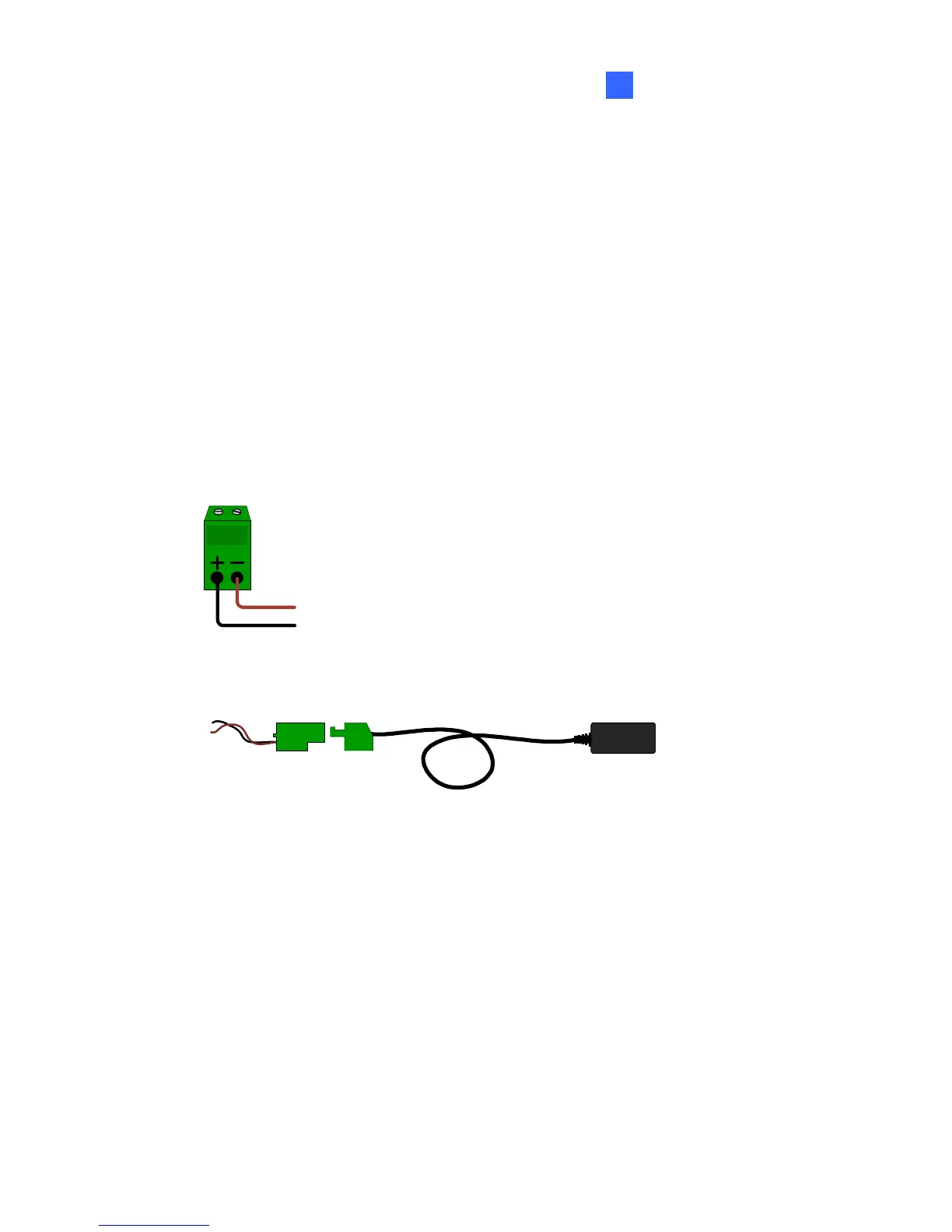
Plug the power adaptor to the terminal block as shown below.
1. Insert the black wire of the Bullet Camera to the left pin (+) and the
brown wire to the right pin (-).
2. Connect the DC 12V Power Adapter to the Terminal Block.
DC 12V Power Adaptor
Terminal Block

Table of Contents

Other manuals for GeoVision GV-IPCamera Series

Questions and Answers:

Question and Answer IconNeed help?

Do you have a question about the GeoVision GV-IPCamera Series and is the answer not in the manual?

GeoVision GV-IPCamera Series Specifications

General IconGeneral
BrandGeoVision
ModelGV-IPCamera Series
CategorySecurity Camera
LanguageEnglish

Related product manuals