EasyManuals Logo

GeoVision GV-IPCamera Series User Manual

GeoVision GV-IPCamera Series
306 pages
To Next Page IconTo Next Page
To Previous Page IconTo Previous Page
Page #177 background imageLoading...
Page #177 background image
Vandal Proof IP Dome (Part I)
143
14
14.4 Connecting the Camera
Connect your Vandal Proof IP Dome to power, network and other cables.
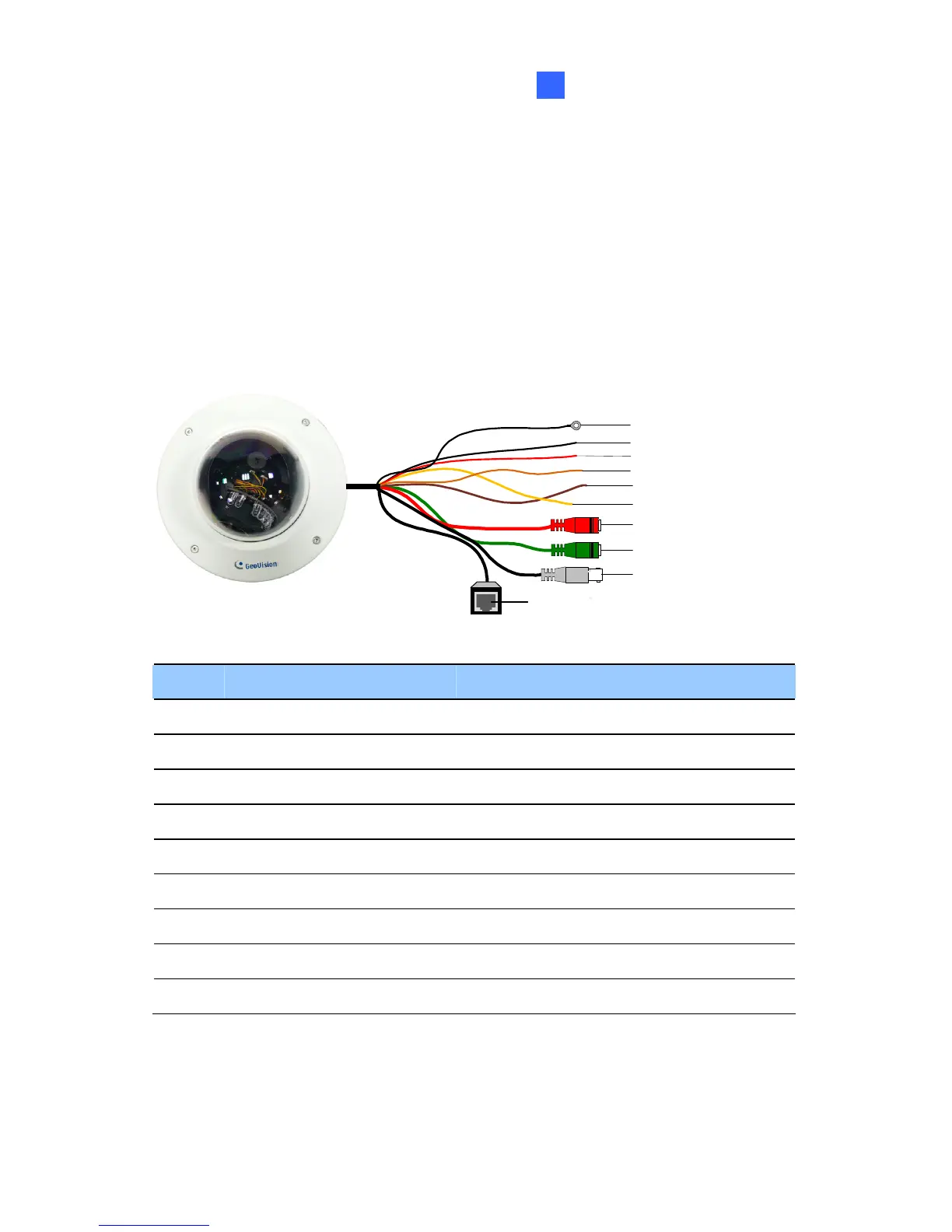
14.4.1 Wire Definition
The cables for Vandal Proof IP Dome are illustrated and defined below.
TV out
Audio out (green)
Audio in (red)
Digital in (oragne)
Ground (yellow)
Digital out (brown)
Shielding ground
DC 12V+ / AC 24V+
DC 12V- / AC 24V-
Ethernet (PoE)
No. Wire Color Definition
1 Black (thick) Shielding Ground
2 Black (thin) DC 12V- / AC 24V-
3 Red DC 12V+ / AC 24V+
4 Orange Digital In
5 Brown Digital out
6 Yellow Ground
7 Red RCA Audio in
8 Green RCA Audio out
9 Black BNC TV out

Table of Contents

Other manuals for GeoVision GV-IPCamera Series

Questions and Answers:

Question and Answer IconNeed help?

Do you have a question about the GeoVision GV-IPCamera Series and is the answer not in the manual?

GeoVision GV-IPCamera Series Specifications

General IconGeneral
BrandGeoVision
ModelGV-IPCamera Series
CategorySecurity Camera
LanguageEnglish

Related product manuals