Target Mini Fixed Rugged Dome
59
7
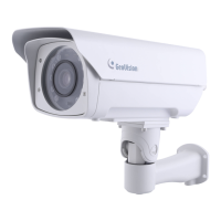
8. Install the supplied waterproof rubber set onto the cable(s). The rubber
set has two parts. According to the below situation, replace Part 1 if
necessary.
For users of PoE with a Cat.5 Ethernet cable, stay with Part 1a
on the camera body.
For users of PoE with a Cat.6 Ethernet cable, change Part 1a to
the supplied Waterproof rubber set (1b).
For users of DC 12V, change Part 1a to the supplied Waterproof
rubber set (1c).
2
For adapter wire
For Ethernet cable
For Cat.5 Ethernet
cable (PoE)
For Cat.6 Ethernet
cable (PoE)
1a
1b 1c
A. Slide the waterproof rubber set, and the waterproof cap you
previously removed through the cable(s) as shown below.
21
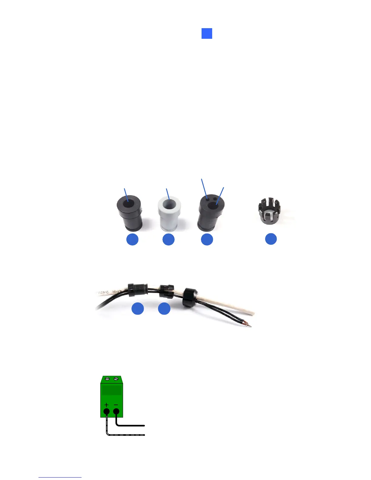
B. Connect the supplied RJ-45 connector to the Ethernet cable.
C. If you are using a power adapter, insert the striped wire to the left
pin (+) and the other wire to the right pin (-).
 Loading...