64 GS15
plus
14. Turn on the plotter power.
After the spindle initializes, look under the carriage to note the position
of the blade as it sits in the carriage spindle.
! The blade should be parallel with the two forks of the lift fork.
! The tip of the blade should point toward the left side of the plotter.
! The spindle pin should be at 12:00 relative to the front of the plotter.
15. If the tool is aligned correctly, go to step 25.
16. If the tool is not aligned correctly, turn off the plotter power.
17. Remove all tools and materials from the plotter.
18. To remove the rear cover (with molded tool rack), lay the plotter on
its left side. Remove (2) Phillips head screws from the bottom edge.
Stand the plotter upright. Lift the rear cover straight up.
CAUTION: Do not rest the plotter on its right side. Do not use the
way shaft to lift or turn the plotter.
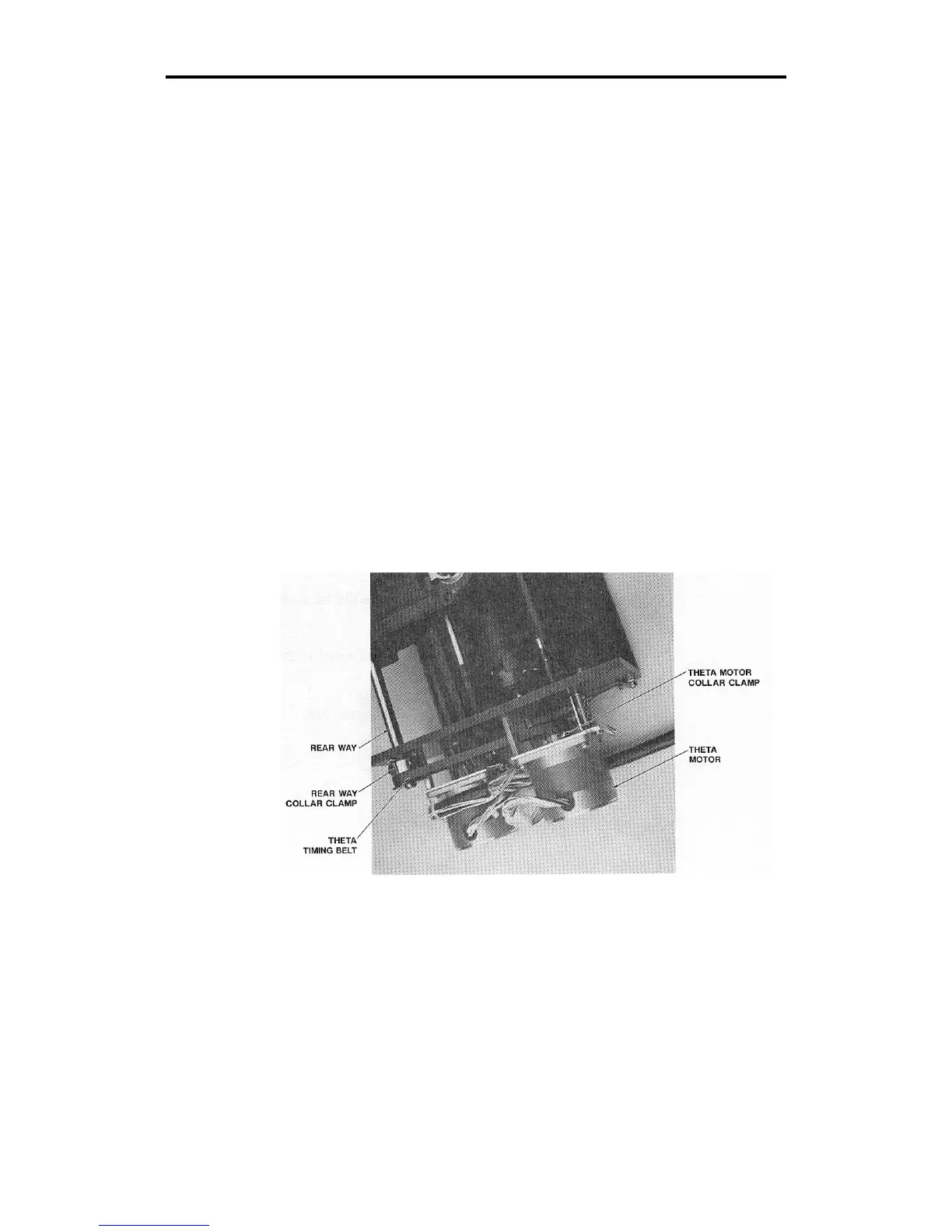
19. Locate the theta motor collar clamp. Use the Allen wrench to ensure
that the set screw in the collar clamp is tightened securely.