Rota –Disc* Working angle adjustment
Working angle (basic position)
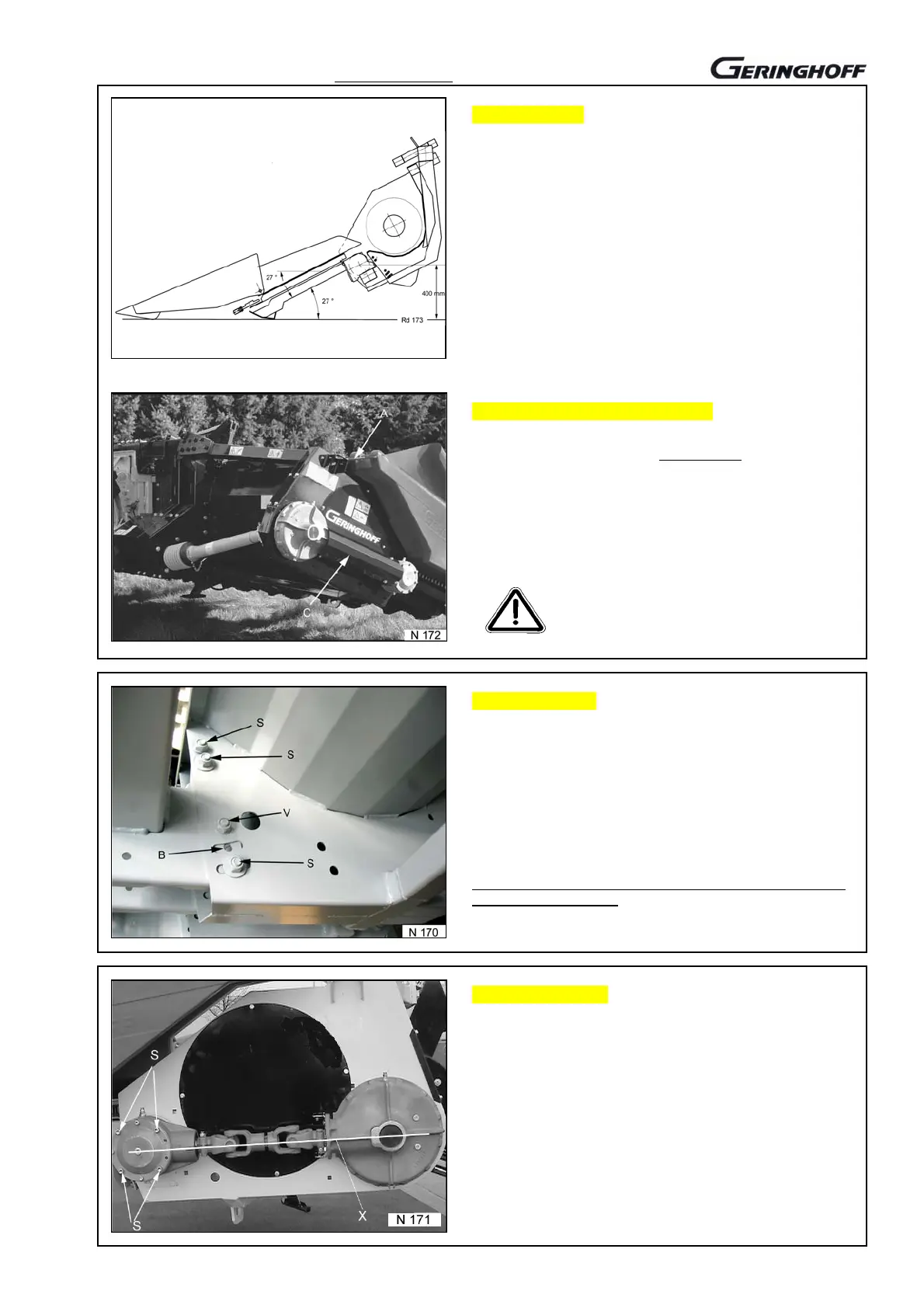
working angle of 27° is factor
-set. If the combine is fitted
with larger or smaller tires than the series equipment, we
recommend checking the working angle. The same applies
also to crawlers.
The real angle is to be determined with ease by placing an
adjustable angle on the stripping plates in working position
and a bubble level.
This check should be made on real working conditions on
the field with the usual ground spacing.
When putting the header down to 27°, a control dimension
of about 400 mm of shaft spacing to the ground will result.
Adjustment of the working angle
Combine and corn header, completely mounted, to put
down in working position on a level surface.
Screwing of the outer bodywork suspension on the frame to
remove.
Guard (C) of the gear drive to remove.
On foldable headers, the locking must absolutely be
activated in working position (see 09/240).
Header, completely relieved but firmly
connected to the combine, to be put
down to the
round!
Adjusting device
When the machine has been put down, first the screw (V) to
remove from all frame connections and to put into the bore
(B).
Then, screws (S) on all frame connections, also on the
sidewalls, slightly to loosen for allowing the elements to be
moved to each other.
The required working angle to adjust via the lifting device of
the combine (header to lift and/or lower).
Then all screws of the frame connection to retighten with the
header being put down!
Drive gear to align
Corn header with the gathering channel to lift and secure
against unwanted lowering.
Only the four screws (S) Sw 8 of the angular gear and the
four screws of the contrate gear fastening on the backside
to loosen. Both the gears to turn until reaching the exact
alignment (see line X).
Gear to refasten and guard to remount.
Outer framework to be connected again. If required,
spacing to be compensated by spacers.
09 / 840