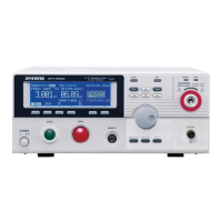
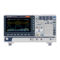
Do you have a question about the GW Instek MSO-2000EA and is the answer not in the manual?
Provides essential safety guidelines for operating and handling the instrument.
Guides users through initial setup procedures, including tilt stand and power connection.
Details how to use automatic measurement functions and items like Voltage/Current, Time, and Delay.
Configures serial and parallel bus inputs, including bus display and decoding.
Configures conditions for capturing waveforms, including trigger types, sources, and parameters.
Outlines how to use the logic analyzer for measuring discrete inputs or bus values.
Details the AWG's dual-channel arbitrary waveform generation capabilities.
Covers creating, editing, recalling, and saving arbitrary waveforms.
Checks if waveforms fit user-specified boundaries and sets conditions for violations.
Creates shape templates for comparing input signals with a defined shape.
Covers saving panel setups, waveforms, images, and other data to internal memory or USB.
Configures USB and Ethernet interfaces for remote control and checks functionality.
Guides on connecting and configuring the USB interface for PC communication.
Sets up the Ethernet interface for remote control via socket server connection.
Enables and configures socket server functionality for LAN communication with a client PC.
Guides through the self-calibration procedure for vertical accuracy.
Details the procedure for compensating the oscilloscope probe for accurate measurements.
Provides instructions for downloading and installing new firmware via USB.
| Bandwidth | 200 MHz |
|---|---|
| Vertical Resolution | 8 bits |
| Display | 7 inch color LCD |
| Vertical Sensitivity | 1 mV/div to 10 V/div |
| Trigger Modes | Edge, Pulse, Video, Slope, Alternate |
| Interface | USB Host, USB Device |
| Channels | 2 analog + 16 digital |


