Do you have a question about the GW Instek PEL-3000 Series and is the answer not in the manual?
Defines graphical symbols used for warnings and cautions in the manual and on the instrument.
Details AC input voltage range, frequency, and power specifications for safe operation.
Provides instructions for safe and proper cleaning procedures using appropriate materials.
Specifies environmental conditions like location, temperature, humidity, altitude for optimal performance.
Outlines recommended storage conditions to maintain instrument integrity.
Provides guidance on the proper and environmentally responsible disposal of electronic equipment.
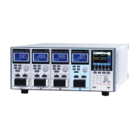
Provides an overview of the PEL-3000(H) series DC electronic loads and their capabilities.
Lists the available DC electronic load models and booster pack models in the series.
Highlights key performance characteristics, features, and interface options of the PEL-3000(H) series.
Lists and describes standard and optional accessories included with the PEL-3000(H) unit.
Details the items included in the product package to ensure all components are present upon delivery.
Provides a visual guide to the front and rear panels of the PEL-3000(H) units.
Describes the layout and function of controls and indicators on the front panel of the instrument.
Details the connectors, ports, and other features located on the rear panel of the instrument.
Explains options for installing the PEL-3000(H) into standard equipment racks using specific mounting kits.
Guides the user through the initial power-on sequence and the instrument's self-test procedure.
Instructs on how to restore factory default configurations to ensure a known initial state.
Details the procedure for setting the internal clock for accurate time-stamping of operations.
Provides considerations and guidance on selecting appropriate wire gauge for load connections to ensure safety and performance.
Explains how to correctly connect load wires to the instrument's input terminals, emphasizing polarity.
Describes the procedure for connecting loads to the front panel input terminals, including safety precautions.
Details how to connect loads to the rear panel input terminals, including safety measures.
Explains how to install the PEL-011 terminal cover for safety and proper connection management.
Describes the use of the PEL-013 flexible terminal cover for managing thicker load wiring or parallel connections.
Explains the purpose and connection of the remote sense terminals for accurate voltage measurements.
Provides instructions on how to check and update the instrument's firmware to the latest version.
Outlines conventions used in the manual for key operations and interface elements for user clarity.
Details the fundamental operating modes (CC, CR, CV, CP, +CV) and basic functions like load on/off and shorting.
Covers common settings like switching functions, slew rates, and response speeds applicable across multiple modes.
Explains advanced settings such as soft start, von voltage, latches, delays, timers, and auto load configurations.
Describes how to set parameter resolution using step and cursor modes for precise editing.
Details protection functions like OCP, OPP, UVP, OVP, RVP, UnReg, Para, ROCP, ROPP, and their configurations.
Covers miscellaneous system settings including speaker, display, alarm tones, language, and trigger configurations.
Explains how to set pass/fail limits and perform Go-NoGo tests for automated quality checks.
Covers saving and recalling settings, presets, memory data, and sequences to internal memory or USB.
Provides an overview of the function menu's purpose and access to various operational modes.
Guides on how to enable or disable specific functions like Program, Sequence, OCP, OPP, and BATT tests.
Details how to create, configure, and run programs consisting of multiple load steps for automated testing.
Explains the creation and execution of normal and fast sequences for complex load simulations.
Describes the automated test procedure for verifying Over Current Protection (OCP) of power supplies.
Details the automated test for Over Power Protection (OPP) of power supply products.
Explains how to perform automated battery discharge tests to evaluate battery performance.
Covers controlling the instrument using analog voltage or resistance signals via external connectors.
Explains how to connect multiple units in parallel to increase total power capacity and manage master/slave configurations.
Details how to configure USB, GPIB, and RS232 interfaces for remote operation and communication.
Guides on verifying remote control functionality via RS232/USB and GPIB interfaces using specific software.
Provides instructions for replacing the dust filter to maintain optimal performance and prevent malfunction.
Details the procedure for replacing the user-replaceable battery that maintains the system clock.
Explains the steps for installing the optional GPIB card if needed for communication.
Lists the factory default configuration settings for various parameters of the PEL-3000(H) instrument.
Provides detailed pin assignments and descriptions for the J1, J2, and Monitor Out connectors.
Explains the characteristics and behavior of each operating mode (CC, CR, CV, CP, +CV) with diagrams.
Displays graphical representations of the operating voltage and current ranges for different models and settings.
Lists the detailed technical specifications, ratings, and performance parameters for the PEL-3000(H) series.
| Brand | GW Instek |
|---|---|
| Model | PEL-3000 Series |
| Category | Test Equipment |
| Language | English |