Harris ADC Device Server User’s Guide
6-2 M/C Switcher Configuration
Dimensions
Input Crosspoints: Specify the input crosspoint on a cascaded switcher to which the
device’s setting is connected. The valid range is 0 to 32768. Default is 16.
Output Crosspoints: Specify the output crosspoint on a cascaded switcher to which the
device’s setting is connected. The valid range is 0 to 32768. Default is 1.
Latency
Switcher Latency: This parameter adjusts the latency of the switcher. The adjustment can
range from -10 to +10 frames. If the adjustment is positive, the switcher switches the
entered number of frames later. If the adjustment is negative, the switcher switches the
entered number of frames earlier. The default value of zero is usually sufficient.
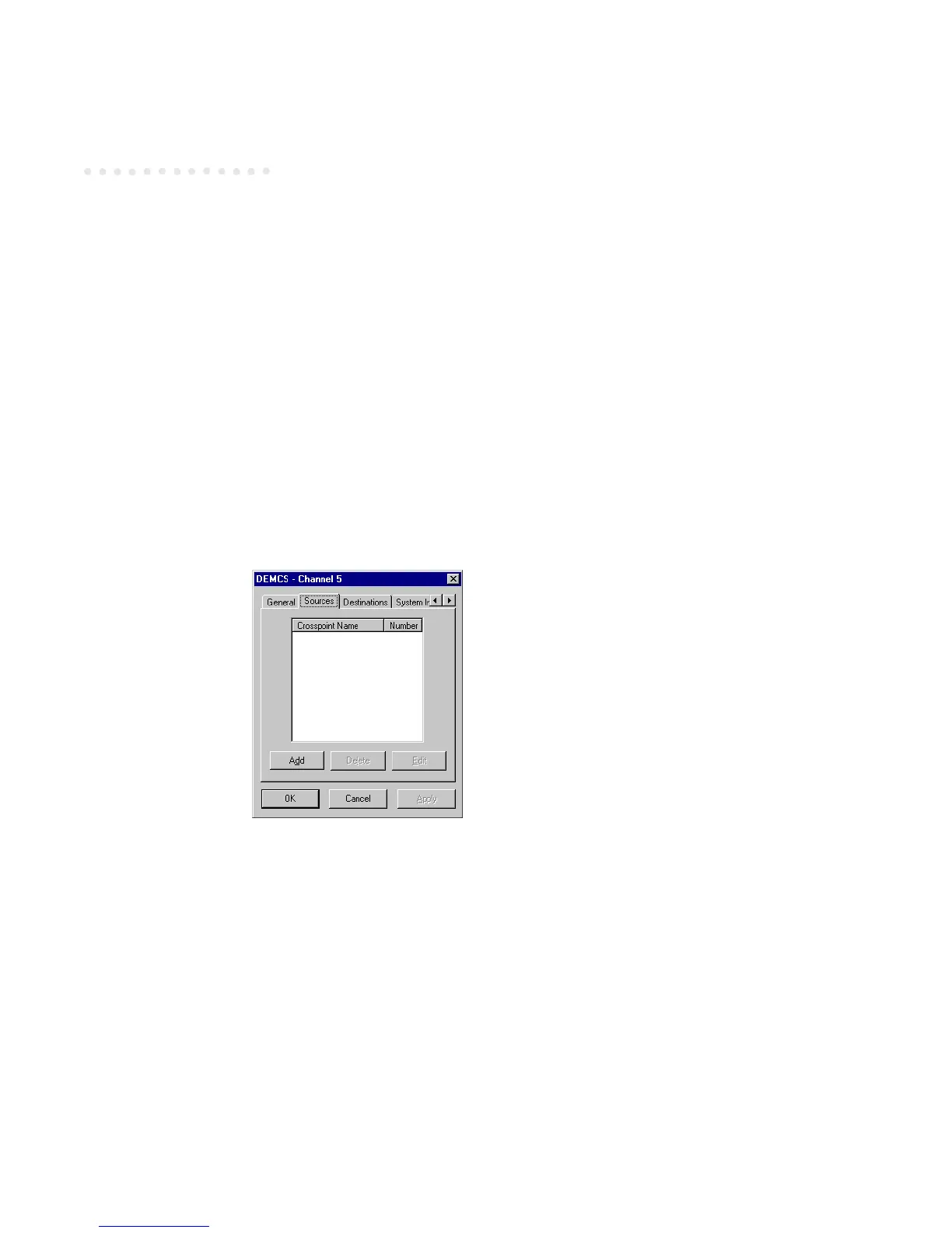
Sources Tab
Crosspoint Name
Click the Add button to enter a source crosspoint name and number:
 Loading...