Harris ADC Device Server User’s Guide
6-8 M/C Switcher Configuration
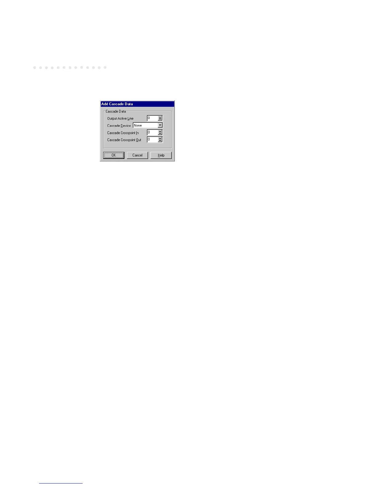
Cascade Data
Output Active Line: This setting specifies which of the switcher’s crosspoints the cascaded
switcher is connected to. The valid range is 0 to 32768. Default is 0.
Cascade Device: Select a cascade device from the dropdown list.
Cascade Crosspoint In: The crosspoint on the cascaded switcher to which the Output Active
Line setting (above) is connected. The valid range is 0 to 32768. Default is 0.
Cascade Crosspoint Out: The out crosspoint on the cascaded switcher to which the signal is
to be routed. The valid range is 0 to 32768. Default is 0.
 Loading...