Electrical connections, LEDs
22
a4643-1.0 HBM: public ClipX
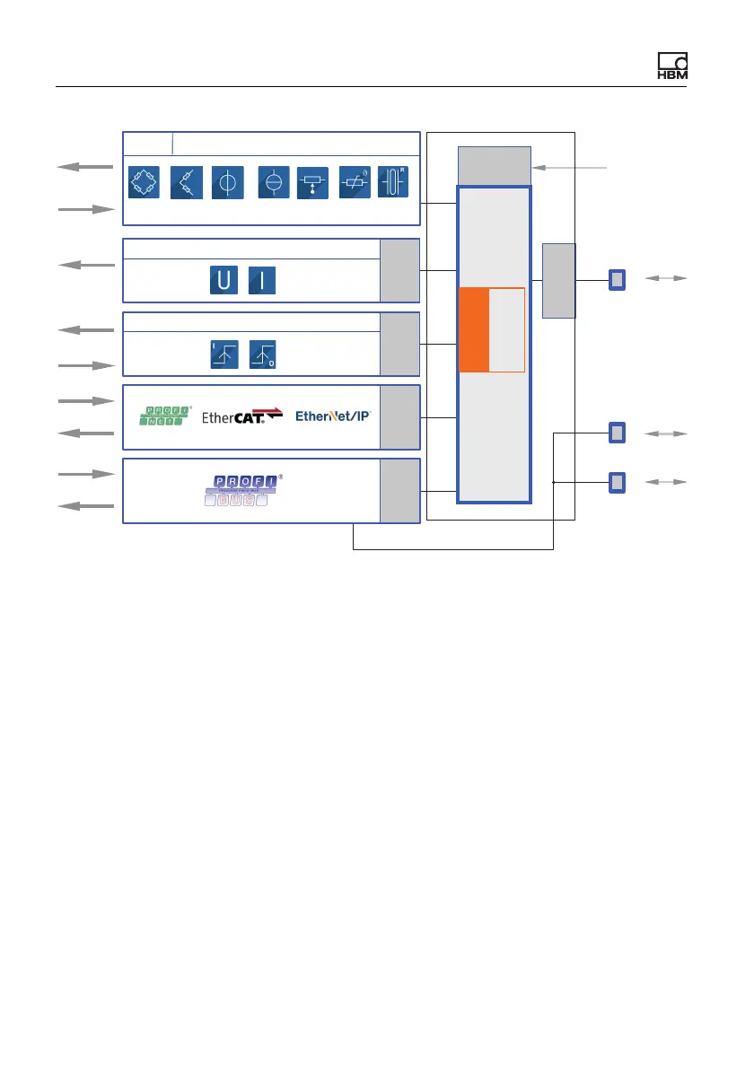
Fig. 6: Function blocks and electrical isolation of the ClipX
Electrical isolation of the GND connections
The following connections are electrically isolated from each other:
• DI, GND (Ground) Digital-In: Reference potential for DI1 and DI2.
• X, GND ClipX bus: Reference potential for ClipX bus (CxA, CxB) and Sync;
on the BM40PB PROFIBUS-GND is also connected by this.
• AI, GND Analog-In: Reference potential for U-In and I-In; the adjacent mea-
surement inputs for voltage and current.
• S GND for the inner shield on double-shielded cable; with 1-wire TEDS,
TEDS (–) is also connected here.
• AO, GND Analog-Out: Reference potential for the analog output.
Galvanic
isolation
TEDS
Transducer
DC / CF
Signal
Signal
Signal
DO 1/2
DO GND
DI 1/2
DI GND
Signal
Bridge
excitation
Galvanic
isolation
Galvanic
isolation
Galvanic
isolation
Analog output
Digital I/Os
FPU
Floating point
unit
Galvanic
isolation
Galvanic
isolation
Ethernet
ClipX SYNC
24 V
0 V
ClipX bus
CPU


 To Next Page