Electrical connections, LEDs
48
a4643-1.0 HBM: public ClipX
6.8 Connecting the analog output
You can output voltage (±10V) or current (4 … 20mA). The analog output is
short-circuit-proof, the bandwidth is 3.8kHz, the update rate is 19.2kHz.
See also Available connections and LEDs
.
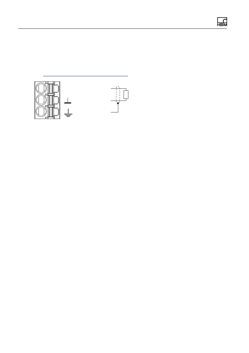
Fig. 24: Plug terminal X2, pin assignment for analog output
Start-up behavior
On starting up the ClipX (power on), the analog output initially has a high output
resistance. After initializing, the status of the settings is determined by the Boot
parameter set.
The factory default setting is: Output deactivated, gross signal as input (source),
zero value 0V, scaling 0/0 and 5/5, value in case of “invalid” signal 0V and test
signal 0V (both inactive).
Value in case of error
Which value is outputted depends on whether you activate the value in case of
an “invalid” signal or not. Make the setting via the ClipX web server in your
browser.
1. Value in case of “invalid” signal active (switch in browser on the right and
red)
If the input signal becomes invalid, or the output signal would be outside the
range of ±11V or less than 3mA or greater than 21mA, the specified value is
outputted.
2. Value in case of “invalid” signal not active (switch in browser on the left and
gray)
The highest or lowest possible value is outputted depending on the signal
(±11V, or 3mA or 21mA).
AO
AO
Plug terminal X3,
analog output
Analog-Out ‒
Cable shield
Analog-Out +