Operation via fieldbus
ClipX
a4643-1.0 HBM: public 97
8.6 Flags and status bits
The following sections set out the assignments of the individual bits to the var-
ious functions for the three status fields for measured value status, system
status and flags, and the bits of the control word.
8.6.1 Measured value status: List of status bits
The following table sets out the bits in the measured value status (32bits) if the
signal in question is invalid.
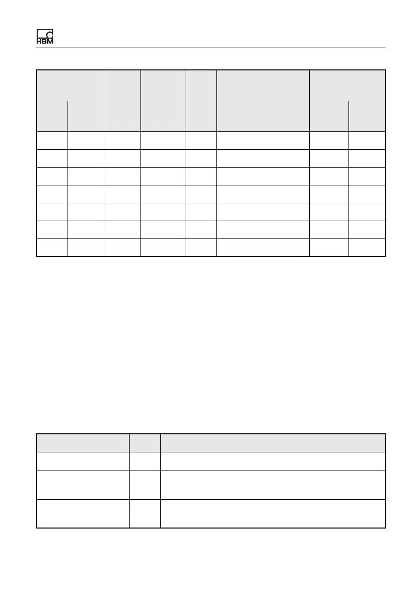
9 44 4 FLOAT RW User signal 4 0x5003 4
9 45 4 FLOAT RW User signal 5 0x5003 5
9 46 4 FLOAT RW User signal 6 0x5003 6
9 47 4 FLOAT RW User signal 7 0x5003 7
9 48 4 FLOAT RW User signal 8 0x5003 8
9 49 4 FLOAT RW User signal 9 0x5003 9
9 50 4 FLOAT RW User signal 10 0x5003 10
Explanation Bit Explanation
ADC 0 Output signal of the A/D converter in digits.
ADC filtered
1
Output signal of the A/D converter after filtering (low-
pass filter) in digits.
Electrical value (field
value)
2
Input signal in the unit of the measured variable, e.g. in
mV/V.
DPV1
No of
bytes
Data
type
R/W Description
ClipX object
directory
Slot Index Index
Sub-
index