Electrical connections, LEDs
ClipX
a4643-1.0 HBM: public 47
Digital outputs
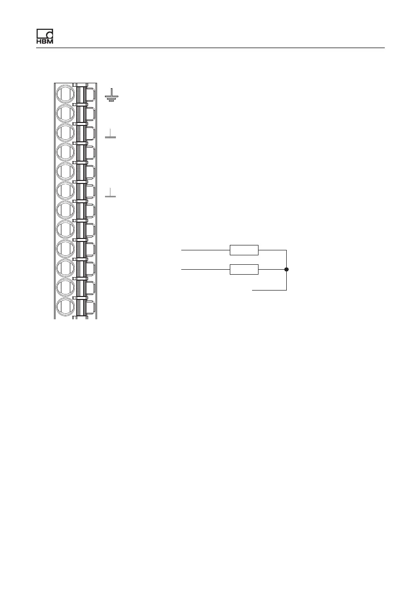
Fig. 23: Plug terminal X2, pin assignment of digital outputs
Start-up behavior of the digital outputs
On starting up the ClipX (power on), each output initially has a high output resis-
tance. After initializing, the status of the settings is determined in the Start
parameter set. When an output is active, the supply voltage (10 … 30V) is
switched through to it.
The factory default setting is: Output deactivated.
DI2
DI1
DO2
DO1
0V
24V
X
DI
Plug terminal X2, supply, DIO, Sync, ClipX bus
Housing, cable shield optional
ClipX bus
ClipX bus GND
ClipX bus
Synchronization
Digital In GND
Digital In 2
Digital In 1
Digital Out 2
Digital Out 1
Supply 0 V and Digital Out GND
Supply 10 … 30 V
CxA
Sync
CxB
 Loading...


