Electrical connections, LEDs
ClipX
a4643-1.0 HBM: public 41
6.6.3 Potentiometric transducer
See also Available connections and LEDs
, Shielding and grounding design.
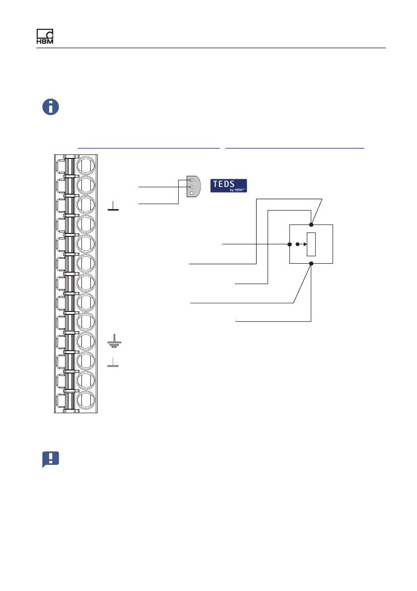
Fig. 17: Plug terminal X4, pin assignment for potentiometric transducer
The use of TEDS is not yet supported by the current firmware version.
It will be in one of the future versions however.
3
2
1wh
gy
bk
gn
bu
Pt100
TEDS
Pt100
Plug terminal X4, transducer connection
1
2'
3
3'
2
I
U
AI
S
4
Measurement signal +
Sense lead -
Bridge excitation voltage +
Sense lead +
Bridge excitation voltage -
Outer cable shield
Inner cable shield
Measurement signal -
1-Wire-TEDS
1
2
Important: Connect the sense leads to the corresponding excitation
voltage leads by wire bridges (2 at 2' and 3 at 3') if you are not using
a 6-wire configuration (with 5 wires assigned). Otherwise a sensor er-
ror will be signaled, and you will not be able to measure (invalid mea-
sured value).
 Loading...


