Electrical connections, LEDs
46
a4643-1.0 HBM: public ClipX
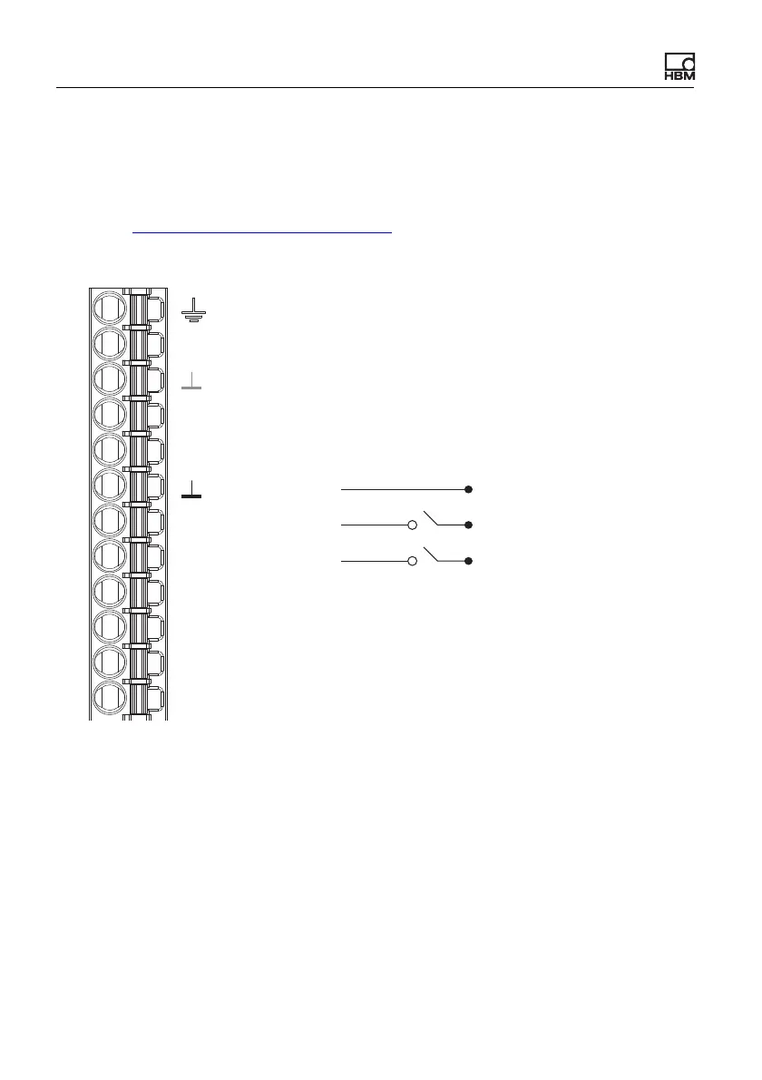
6.7 Connecting the digital inputs and outputs
The digital inputs and the flags or bits for the outputs are analyzed after 1ms at
the latest in the event of a change.
See also Available connections and LEDs
.
Digital inputs
Fig. 22: Plug terminal X2, pin assignment of digital inputs
The digital inputs must be switched against a positive voltage (≥10V). An open
input will be detected as LOW.
DI2
DI1
DI
DO2
DO1
0V
24V
X
Plug terminal X2, supply, DIO, Sync, ClipX bus
Housing, cable shield optional
ClipX bus
ClipX bus GND
ClipX bus
Sync Synchronization
Digital In GND
Digital In 2
Digital In 1
Digital Out 2
Digital Out 1
Supply 0 V and Digital Out GND
Supply 10 … 30 V
CxA
CxB
LOW: 0 V … 5 V
HIGH: 10 V … 30 V