2 a4643-1.0 HBM: public ClipX
Contents Page
1 Safety instructions . . . . . . . . . . . . . . . . . . . . . . . . . . . . . . . . . . . . . . . 5
2 Symbols on the instrument . . . . . . . . . . . . . . . . . . . . . . . . . . . . . . . . 9
3 Overview . . . . . . . . . . . . . . . . . . . . . . . . . . . . . . . . . . . . . . . . . . . . . . 11
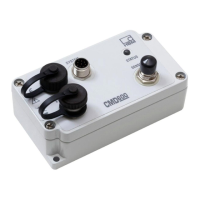
4 ClipX device types, scope of supply. . . . . . . . . . . . . . . . . . . . . . . . 13
4.1 Device types . . . . . . . . . . . . . . . . . . . . . . . . . . . . . . . . . . . . . . . . . . . . 13
4.2 Scope of supply . . . . . . . . . . . . . . . . . . . . . . . . . . . . . . . . . . . . . . . . . 14
4.3 Dimensions . . . . . . . . . . . . . . . . . . . . . . . . . . . . . . . . . . . . . . . . . . . . . 16
5 Mounting . . . . . . . . . . . . . . . . . . . . . . . . . . . . . . . . . . . . . . . . . . . . . . 17
5.1 Mounting on a support rail . . . . . . . . . . . . . . . . . . . . . . . . . . . . . . . . . 17
5.2 Dismounting from a support rail . . . . . . . . . . . . . . . . . . . . . . . . . . . . . 18
5.3 Other mounting options. . . . . . . . . . . . . . . . . . . . . . . . . . . . . . . . . . . . 19
6 Electrical connections, LEDs. . . . . . . . . . . . . . . . . . . . . . . . . . . . . . 21
6.1 Functionality (block diagram) . . . . . . . . . . . . . . . . . . . . . . . . . . . . . . . 21
6.2 Shielding and grounding design . . . . . . . . . . . . . . . . . . . . . . . . . . . . . 23
6.3 Available connections and LEDs . . . . . . . . . . . . . . . . . . . . . . . . . . . . 24
6.4 Health monitoring, LEDs . . . . . . . . . . . . . . . . . . . . . . . . . . . . . . . . . . . 26
6.5 Connecting the supply voltage . . . . . . . . . . . . . . . . . . . . . . . . . . . . . . 33
6.6 Connecting transducers . . . . . . . . . . . . . . . . . . . . . . . . . . . . . . . . . . . 34
6.6.1 Strain gage full and half bridge, voltage-fed piezo-resistive sensors . 34
6.6.2 Strain gage full bridge for applications in areas with potentially
explosive atmospheres . . . . . . . . . . . . . . . . . . . . . . . . . . . . . . . . . . . . 40
6.6.3 Potentiometric transducer . . . . . . . . . . . . . . . . . . . . . . . . . . . . . . . . . . 41
6.6.4 Temperature measurement by Pt100 . . . . . . . . . . . . . . . . . . . . . . . . . 42
6.6.5 Voltage source (±10V) . . . . . . . . . . . . . . . . . . . . . . . . . . . . . . . . . . . . 43
6.6.6 Current source (±20mA or 4 … 20mA). . . . . . . . . . . . . . . . . . . . . . . . 44
6.6.7 Current drain (4 … 20mA) . . . . . . . . . . . . . . . . . . . . . . . . . . . . . . . . . 45
6.7 Connecting the digital inputs and outputs. . . . . . . . . . . . . . . . . . . . . . 46
6.8 Connecting the analog output. . . . . . . . . . . . . . . . . . . . . . . . . . . . . . . 48
6.9 Using multiple ClipX devices, ClipX bus . . . . . . . . . . . . . . . . . . . . . . . 49
6.10 Synchronizing multiple ClipX CF amplifiers . . . . . . . . . . . . . . . . . . . . 51
6.11 Signal propagation times within the ClipX and over the ClipX bus . . . 53