Electrical connections, LEDs
54
a4643-1.0 HBM: public ClipX
Some signals might also have sources from other groups. For example, the
analog output might deliver a signal from the ClipX bus. In these cases,you
must add the propagation time of the source signal's group in order to get the
total propagation time.
Example 1
Propagation time from input, e.g. 10V, 20mA or DC full/half bridge, to analog
output (10V) with a Bessel filter at 1kHz:
• A/D converter (ADC): 260µs
• Filter: 0.43/1000 = 430µs
• Analog output: 52µs
Added to this is a jitter of up to 52µs, as the A/D converter only starts a new con-
version every 52µs. So the total propagation time is 742 … 797µs.
Group 2: Flags, Digital I/Os, calculated values, ClipX bus
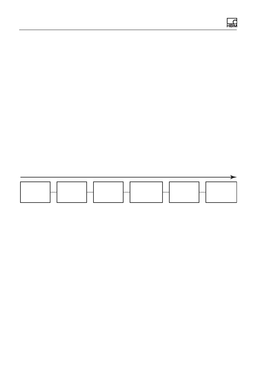
Fig. 30: Maximum propagation time for group 2: 1ms
Example 2
Propagation time from input (see group 1) to a digital output with a Bessel filter
at 1kHz, limit value switch at half the step height.
• A/D converter (ADC): 260µs
• Filter: 0.43/1000 = 430µs
•Group 2: 1ms
• Digital output: max. 250µs response time
1 ms
Flags and
values from
fieldbus
Digitale
inputs
Computed
channels
Digital flags
(I/O flags)
1)
Digital
outputs
2)
ClipX bus:
Start
transfer
3)
1)
Changes in digital flags are analyzed in the following order: Zeroing, taring, clear zero value,
clear tare value, reset limit value switch, reset peak values, hold held values, clear hold values.
3)
Asynchronous transfer of the values on the ClipX bus is complete after max. 1 ms, i.e on the next
cycle.
2)
The digital outputs have an additional response time of max. 0.25 ms.