059305–00 REV. E
HEAT-TIMER CORP.
|
19
04 INSTALLATION INSTRUCTIONS
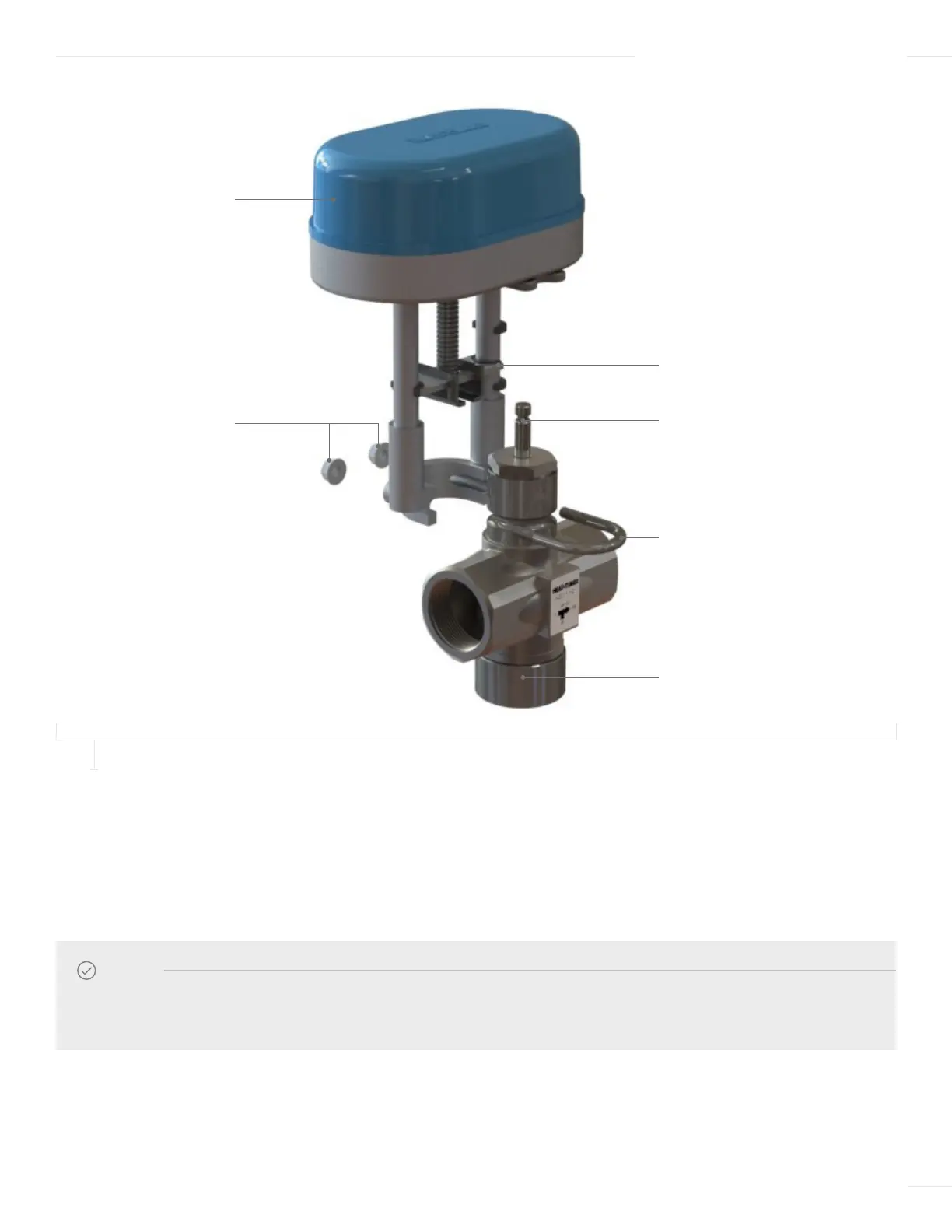
U-CHANNEL
HTC ACTUATOR
LOCKING NUTS
VALVE STEM GROOVE
U-BOLT
STAINLESS VALVE BODY
4 Insert the U-bolt around the valve body groove and into the Actuator assembly.
5 Secure the U-bolt in place with two locking nuts, ensuring the locking nuts are tightened evenly.
6 Once the actuator is completely mounted onto the valve, the actuator cover can be remove to allow access for wiring, setting of
Dip Switch 1 and startup calibration of the actuator. Simply remove the retaining screw on the cover and lift the cover off.
NOTE
The actuator may make a grinding noise if the locking nuts are not tightened evenly and resulting in potential damage to
the actuator motor.
FIGURE 8
MOUNTING THE ACTUATOR TO THE ETV VALVE