coming out of the rack completely and the cover will remain in the rack attached to the rear alignment
brackets.
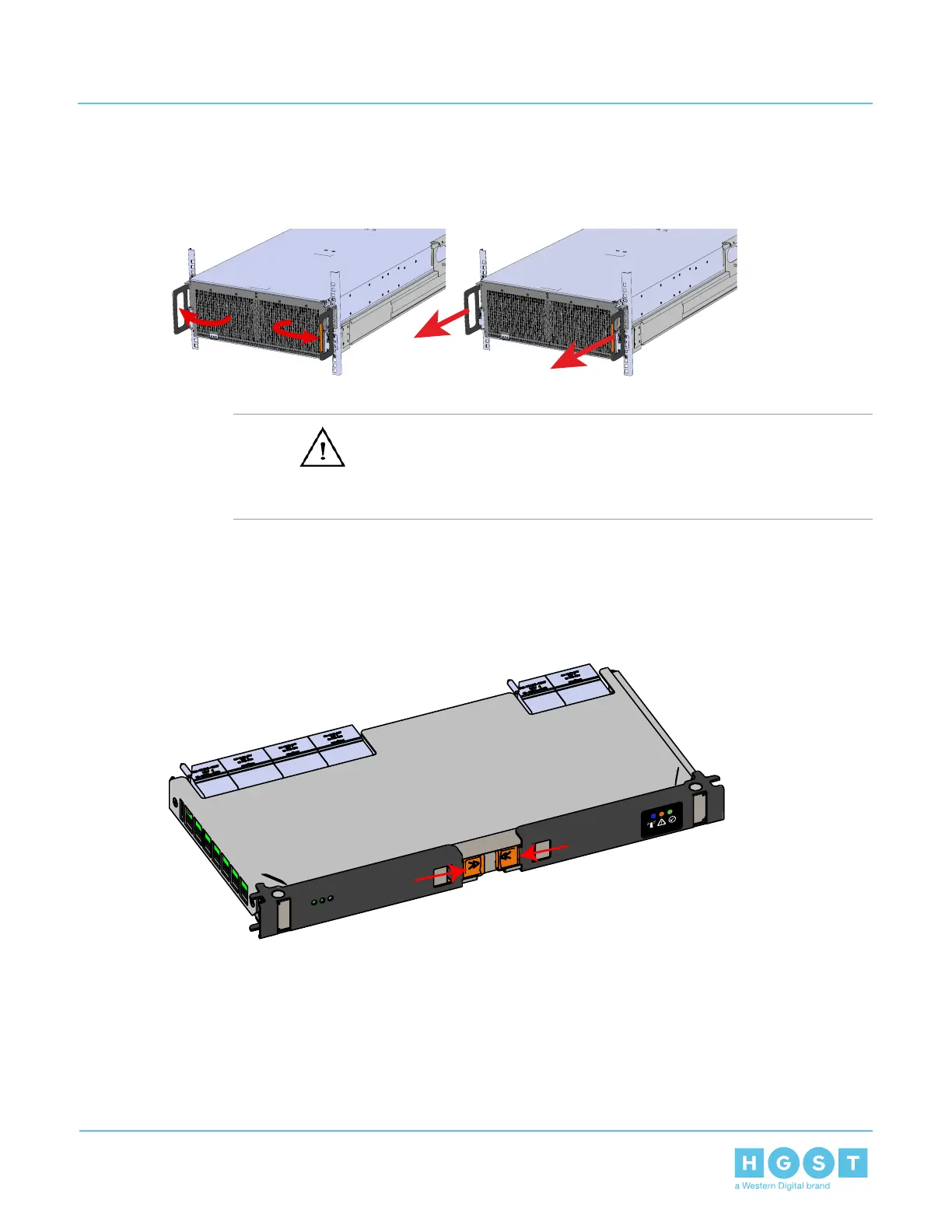
Figure 146: Chassis Handle Operation
34. Install the IOM.
a)
Caution: If a pin on the IOM’s internal connectors is bent or damaged, the IOM will have
to be replaced. For this reason it is imperative that the IOM is not forced into position, that it is
inserted straight, and that the directions for installing the IOM are followed exactly.
b) Ensure that the handles on the IOM are not latched. To unlatch them, press the latch release in the
direction shown in the following image.
Figure 147: Unlatching IOM Handles
c) Align the IOM with the empty slot on the top of the chassis so that the arrow on the IOM latch release
is facing toward the side shown in the following image.
129
4 Part Replacement
User Guide 4.9 Chassis Replacement

 Loading...