DTS-60A OPERATORS MANUAL
4
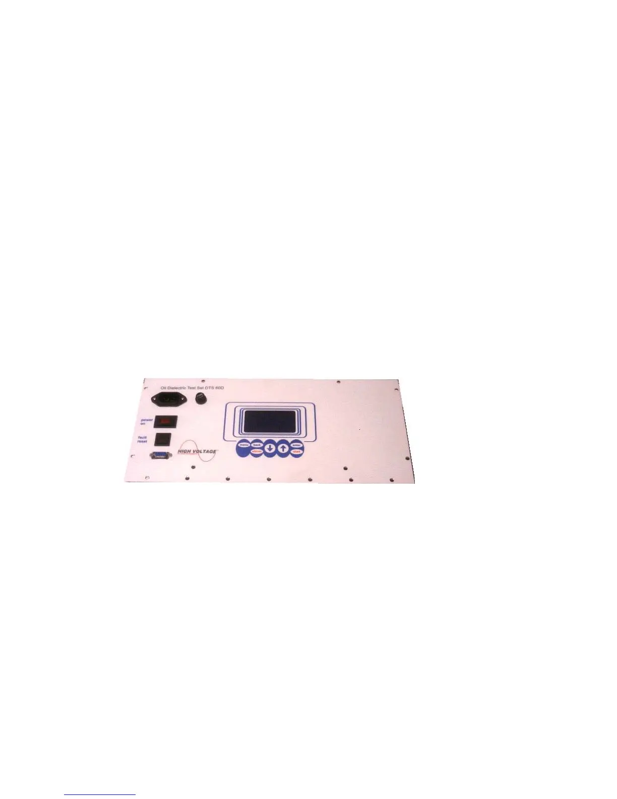
1.2 Control Panel
The equipment’s Control Panel is depicted in Figure 1.1. It
consists of the following:
Input Power
The Input Power connector accepts most standard
electrical equipment type cords. The power supplied to
the input connector must be from a grounded source
rated to match the input power specifications noted in
Table 1.1.
Main Power
The Main Power switch provides the power to the
control and power circuits. The neon lamp will light
when the power is on and the voltage is available
through the input line cord. The Input Power Fuse
located electrically before the Main Power switch
provides line fault protection for the unit.
Fuse Socket
LCD display
The Liquid Crystal Display guides the user to the
system’s functionalities.
Keyboard
Compact 5-key keyboard for equipment operation.
Figure 1.1 – DTS-60A Control Panel