27
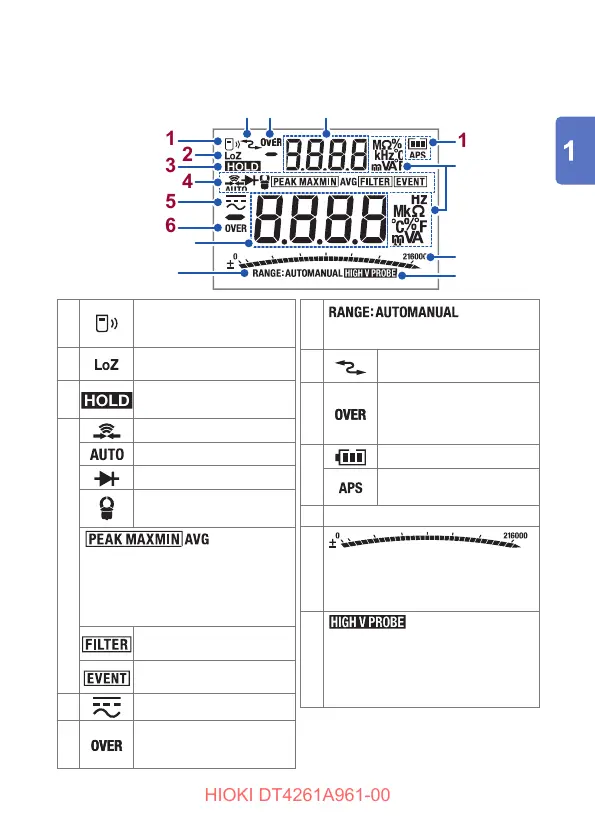
Part Names and Functions
Display
88
11
22
33
44
55
66
1010
1111
1212
77
1313
99
Sub display
Main display
11
Wireless
communications
function (p. 92)
22
Low input impedance
measurement (p. 61)
33
Retention of the
measured value (p. 75)
44
Continuity check (p. 63)
AC/DC automatic judgment
Diode test (p. 64)
Clamp current
measurement (p. 71)
(p. 82)
Maximum value (MAX), minimum
value (MIN), average value (AVG),
maximum value of the peak value
(PEAK MAX), minimum value of
the peak value (PEAK MIN)
Filter function enabled
(p. 79)
Event recording function
(p. 94)
55
AC, DC
66
The measured value in the
main display exceeds the
maximum value of the range.
77
Auto range, manual range (p. 73)
88
Communicating with the
PC (p. 89)
99
The measured value in
the sub display exceeds
the maximum value of
the range.
1010
Battery indicator (p. 28)
Auto power save function
enabled (p. 87)
1111
Each unit
1212
Indication (example): In the case
of 30.00 V input in the 60.00 V
range, the bar is displayed to the
center of the scale.
1313
DC HIGH V PROBE mode*
enabled
* Used when the DC high
voltage probe (on sale soon) is
connected.
For details about the error, see
“6.3 Error and Operation Display”
(p. 135).