11
11
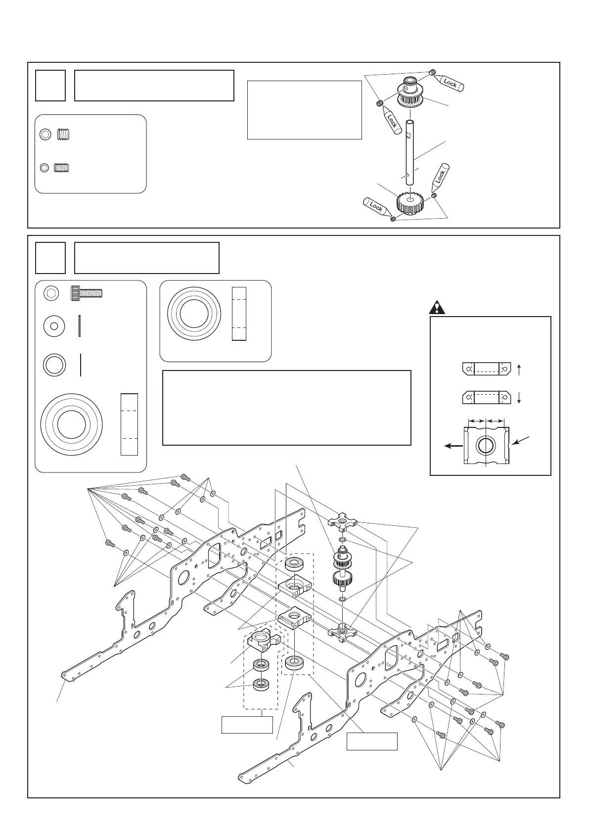
カウンターギヤ部の組立
Counter gear assembly
1
テールプーリー17T (3GT D6)
Tail pulley 17T (3GT D6)
カウンターギヤシャフトD6
Counter gear shaft D6
EXカウンターギヤ21T
EX counter gear 21T
2. 組立編 Assembly
サーボフレームの組立
Servo frame assembly
2
M3X8CS
..............................
18
M3X8CS
M3X8CS
M3X8CS
FW ø2.6Xø7.5X0.5T
............
18
Brg. ø10Xø22X6ZZ
...............
2
FW ø2.6Xø7.5X0.5T
FW ø2.6Xø7.5X0.5T
FW ø2.6Xø7.5X0.5T
FW ø2.6Xø7.5X0.5T
上側
Upper
下側
Lower
ここでは各ネジは仮組とします。
All screws are fastened temporarily.
注 意 Caution
カウンターギヤASSYについて
数フライト後、バックラッシュ及びガタを確認してください。
バックラッシュ及びガタが大きくなっている場合は、ワッシャー
を追加して調整してください。
Counter gear assembly
Check the backlash and looseness after several flights.
If significantly loose, add additional washers to adjust.
Brg. ø10Xø19X5ZZ
...............
2
(注)
(Note)
12.5mm
11.5mm
前
Front
ベアリングホルダーø13
Bearing holder ø13
カウンターギヤASSY
Counter gear assembly
EX-EPサーボフレーム
EX-EP servo frame
EX-EPサーボフレーム
EX-EP servo frame
EX-EPベアリングホルダーø19
EX-EP bearing holder ø19
Brg. ø10Xø19X5ZZ
Brg. ø10Xø22X6ZZ
ベ アリン グ ホ ル ダ ー ø22
Bearing holder ø22
FW ø6Xø8X0.1T
組立済
Pre-assembled
組立済
Pre-assembled
ベアリングホルダーø22の向き
に注意してください。
Be careful with the direction of
the bearing holder ø22.
FW ø6Xø8X0.1T
...................
2
ワッシャーを使って上下の
ガタ取りをしてください。
Use the washers to fill up any gaps
to eliminate any looseness.
M3X5SS
.................................
2
M3X5SS
M4X4SS
M4X4SS
................................
2
ベ アリングホルダーø13を取付
けた時に、上下にアソビが無い
様 に 締 付 け てください 。
Tighten screw so there is no
up/ down play when bearing
holder ø13 is assembled.