38
38
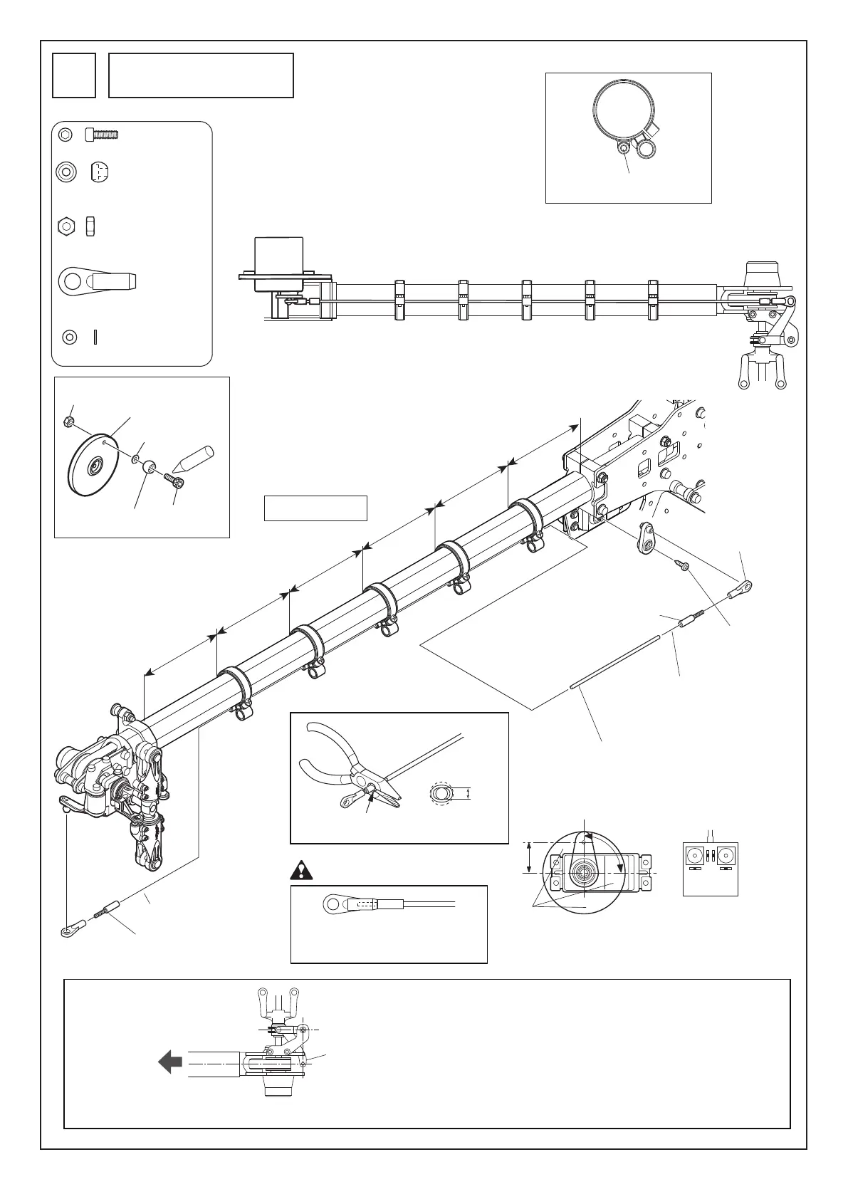
ラダーのリンケージ
Rudder linkage
34
M2ナ ット
M2 nut
サーボホーン
Servo horn
M2X6CS
EX ø5ボール
EX ø5 ball
Lock
FWø1.7
A=B=C=D=E=F
サーボホーン:
ニュートラル
Servo horn:
NEUTRAL
90˚
17mm
カット
Cut
この穴を使 用する
Use this hole.
プロポ
スティック、トリム:
ニュートラル
Radio transmitter
Stick, trim:
NEUTRAL
つぶします
Crush here.
2mm
A
B
C
D
F
E
サーボに付属のネジ
Servo horn screw
included with servo
ア ジ ャ ストジ ョイント M2Xø2
Adjust joint M2Xø2
アジャストジョイントM2Xø2
Adjust joint M2Xø2
M2ロッドエンド
M2 rod end
M2ロ ッド エ ンド
M2 rod end
下図のようにラダーコントロールガイドの位置をラダー
コントロールロッドにそってずらしながら合わせます。
Position the rudder control guide by sliding it along the
rudder control rod as shown below.
テールピッチレバー
Tail pitch lever
上から見た図
Top view
機首方向
Nose
テールブームパイプに対して直角の位置(初期設定)
Perpendicular to the tail boom pipe (initial setting)
ホバリングの回転数によって変化しますので、フライト
をして調整をします。
The position changes depending on the hovering rpm. Adjust it
by actual flight.
M2X6CS
................................
1
FW ø1.7
..................................
1
EX ø5ボール
.........................
1
EX ø5 ball
M2ロッドエンド
..................
2
M2 rod end
M2ナット
..............................
1
M2 nut
エポキシ接着剤(30分以上硬化型)
で接着します。
Bond them with (30 minute type)
epoxy adhesive.
ø2カーボンロッド
ø2 carbon rod
※カーボンロッドはヤスリで
カットして使用します。
※Cut the carbon rod by a file.
注 意 Caution
根本まで完全にねじ込んでください。
Insert the adjust joint into the rod end
completely until there is no gap left.