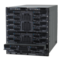
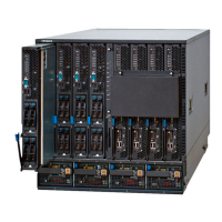
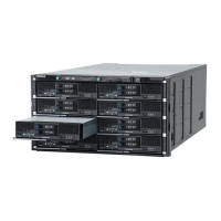
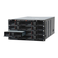
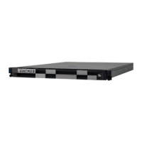
Figure 1-38 Full-wide Server blade (CB 520X B1/B2/B3)
Table 1-30 Server blade switches, indicators, and connectors
No. Name State Description
1 USB port - USB port in the server blade.
2 NMI reset switch - Press this switch to issue Non- Maskable
Interrupt (NMI) of the server blade.
3
KVM port
1
- Provides VGA, serial port and 2 USB
port outputs. Connect a KVM cable to
this port.
4 Power switch with
Power LED
- Press this switch to power-on.
Press and hold this switch for four
seconds or more, it will force the main
power-off.
Green-On Main power of the server blade is
turned on.
Green-Blink Main power of the server blade is
turned off.
5 Location Identify LED
(LID)
Blue-On The server blade is identified.
6 Attention LED (ATN) Amber-On Errors are detected in the server blade.
7 Alarm LED (ALM) Amber-On Any failure that the hardware needs to
be replaced is detected.
8
Primary LED
2
White-On Indicates the blade is primary blade.
(Only for SMP CB 520X B1/B2/B3)
9
QPI Link Fault LED
2
Amber-On An error is detected on QPI link in SMP
configuration.
(Only for SMP CB 520X B1/B2/B3)
10
QPI Link Status LED
2
Green-On QPI Link is linked up in SMP
configuration.
(Only for SMP CB 520X B1/B2/B3)
Introduction
1-27
Hitachi Compute Blade 500 Series System Service Manual
 Loading...


