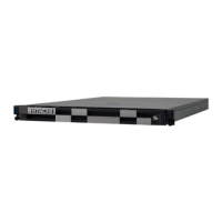
Management module
Figure 1-40 Management module
Table 1-32 LEDs, switches, and connectors on management module
No. Name State Description
1 Management LAN Port #0
(MGMT0)
- -
2 Management LAN Port #1
(MGMT1)
- -
3 Maintenance LAN Port
(MAINT)
- For maintenance personnel.
4 LAN Link Speed LED Amber-On 1000BASE-T
Green-On 100BASE-TX
Off 10BASE-T
5 LAN Status LED Green-On LAN link is established.
Green-Blink LAN is under transmission.
6 Serial Port (SER) - Serial port is for the management
console PC.
7 Shutdown switch (SHDN) - Press it for four seconds or more to turn
off the power.
8 Heartbeat LED (HB) Green-Blink F/W is activated. If this LED is not
blinking, the management module does
not work properly.
Green-On
Off
F/W is not activated.
9 Power LED
(PWR)
Green-On Normal operation.
Green-Blink The system is shutting down or booting
Off Power is not supplied to the server
blade.
10 Identify LED (LID) Blue-On The management module is identified.
11 Alarm LED (ALM) Red-On A serious error has occurred in the
management module.
1-30
Introduction
Hitachi Compute Blade 500 Series System Service Manual

 Loading...