No. Name State Description
and the temperature threshold is
exceeded.)
Off The power fails or no power is supplied.
3 Identify LED (UID) Blue-On The switch module is identified
Off The switch module is not identified
4 Port status LED
(Port No.)
Green-On LAN interfaces online.
Green-Blink Link has been established and also
transmitting and receiving signals are
under way.
Amber-On A signal or communication received, but
not on line.
Green-On /Amber-
On alternatively
Initial diagnosis or initial setting is in
progress.
Off Abnormal power state (Power failure or no
power is supplied).
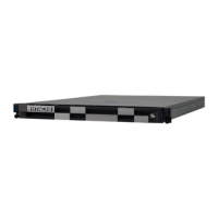
Power supply module
Figure 1-49 Power supply module
Table 1-41 LED and connector on power supply module
No. Name State Description
1 Power LED
(PWR)
Green-On Output main power (12V) properly.
Green-Blink Standby condition (input power is OK).
Amber-On Failures or shutdown the system
Amber-Blink No input power to this power supply, but input power is
supplied to others.
Off No power supplied.
2 Inlet - IEC60320-C20
1-38
Introduction
Hitachi Compute Blade 500 Series System Service Manual

 Loading...