Copyright © 2019, 2021, Hitachi, Ltd.
DKC910IHitachi Proprietary
[INST(IN)03-01-90]
Rev.2
INST(IN)03-01-90
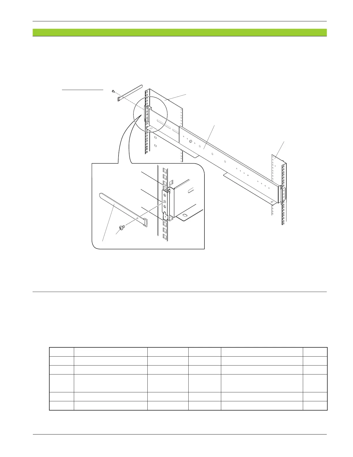
(9) Tighten the screw (SBB-RAIL) and the loop cable tie on the rear edge of the rail to x the rail to
the rack. The xing position is the fourth hole from the bottom of the unit boundary line.
Figure 3-9 Fixing the Rails
(10) Install the rail into the left side of the rack in the same way as procedures Step (6) to Step (9).
The right and left rails are same in shape. Horizontally turn the left rail in the opposite direction of
the right rail (180 degree turn).
3. Installing rails for Drive Box (FBX)
The rail install procedure is different depending on the hole shape (square or circular hole) on the rack.
Check the holes on the rack before the installation work.
Table 3-3 shows the components for the rails for Drive Box (FBX).
Table 3-3 Components for Rail (RRDBF) (Per Unit)
Item No. Product name Parts No. Quantity Comment Remarks
1 Slide Rail 2854551-A 1 set Rail(R) and Rail(L) −
2 Accessory Set − 1 − −
3 Screw 3261898-512 4 For xing Storage System and
rail
(*1)
4 Screw (M4_FLAT) 5550657-A 6 Pin for rectangular hole (*1)
5 Loop cable tie 5552567-1 2 For xing the cable −
*1: These parts are included in Item No. 2 Accessory Set.
Screw (SBB-RAIL)
Rail
Frame (front right side)
Unit boundary
Unit boundary
Unit boundary
Frame (rear right side)
Right side of rack
Loop cable tie