Copyright © 2019, 2021, Hitachi, Ltd.
DKC910IHitachi Proprietary
[INST(IN)02-01-40]
Rev.2
INST(IN)02-01-40
4. Installation Area/Maintenance Area and Earthquake-resistant Plan
(1) Installation area (for one rack) and maintenance area
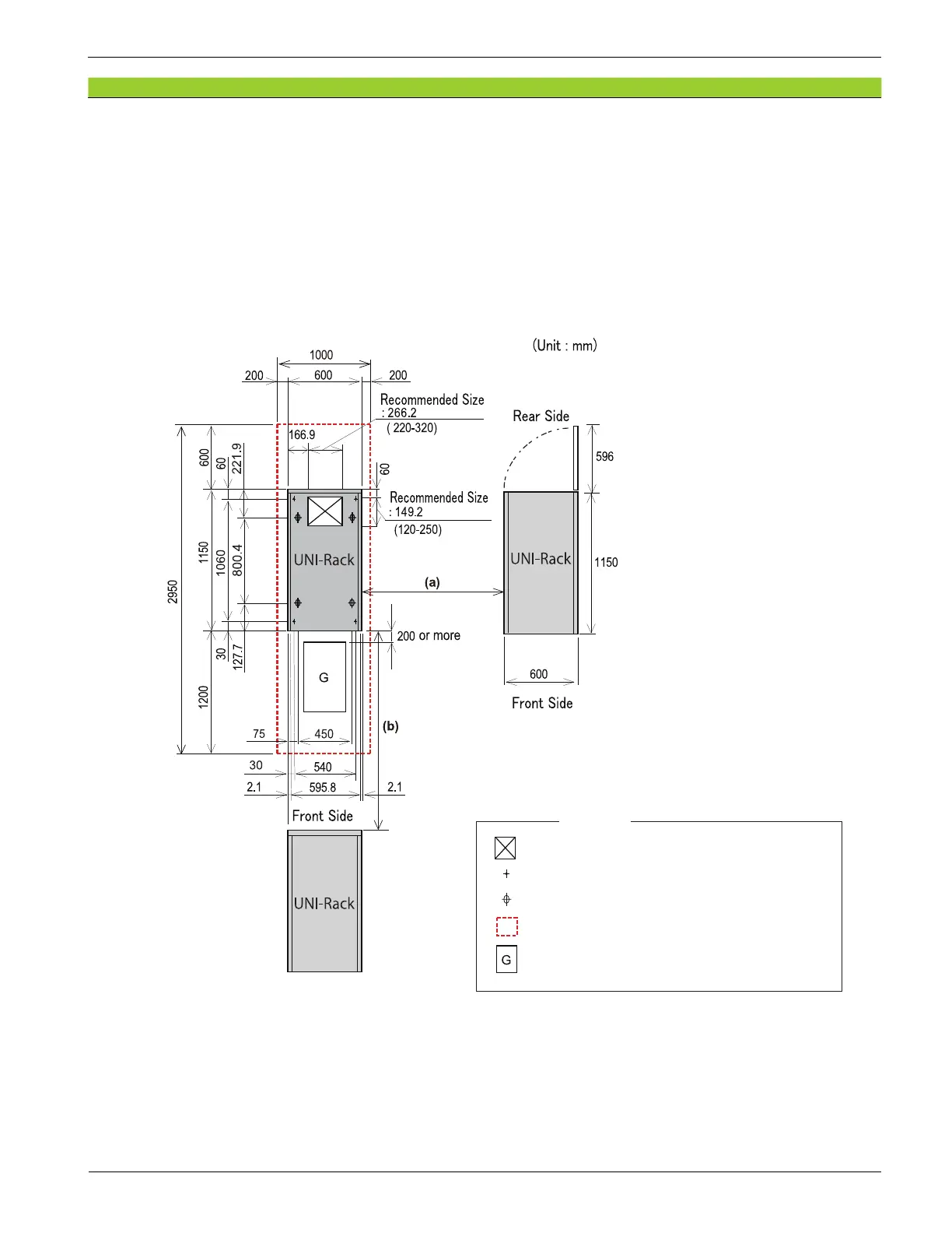
Figure 2-3 shows installation and maintenance areas for the A-6516-RKU3 rack frame and a cut-
out gure using a free access floor.
NOTE : Since installation areas vary depending on the size of systems, layout, and conditions
of buildings, it is required to contact a construction professional of carry-in buildings.
Figure 2-3 Installation and Maintenance Areas of Rack Frame
When the RKU racks are installed, the right and left side clearance (a) and the front and rear side
clearance (b) must be secured. The clearance (a) and the clearance (b) are calculated from the total
weight of the storage system and the floor load capacity.
When installing one RKU rack, calculate the total weight of the storage system according to “(2)
Calculation of total weight of storage system”, and then see one of the tables by floor load capacity
in “(3) Reference matrix of clearances between racks” to nd the values of (a) and (b).
: Holing open part
: Leveling bolt
Symbols
: Caster
: Maintenance area boundary
: Holing open panel
(For the below the floor level ventilation method)