Component Details
GR2K-GA-1002 3-9
Rev. 6.03
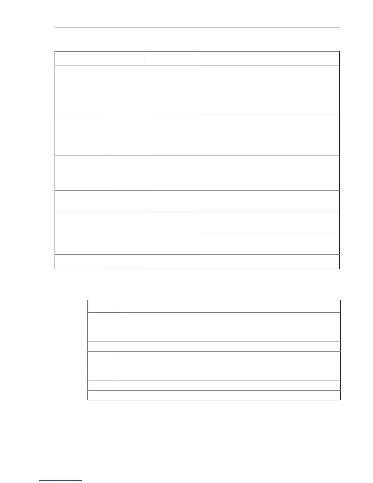
Switch and LED indication
Table 3-6 RM-CPU switch and function of LED indications
Name of switch
and LED
Switch or LED Status Content
STATUS LED: Green/
Yellow/ Red
Shows the
operating
condition of RM.
Green: Operable operation
Yellow : Blocking and the board replaceable state.
Green blinking: Under preparation (Program being
loaded.)
Red: Fault or shutdown
Extinguished: Operation not possible (Including the device
power supply being turned off)
ACTIVE LED: Green Shows the
operating/standby
condition of
duplicated basic
control
mechanism.
Green: Shows the state of operation. (Lights up
continuously when not duplicated.)
Extinguished: Shows the standby state. (Including the
device power supply being turned off.)
POWER LED: Green Shows the state of
power supply
turned on or off.
Green: Voltages of 5V and 3.3V of RMP are normal.
Extinguished: Voltages of 5V and 3.3V of RMP are not the
specified voltage.
(Fault in power supply unit or RMP board, or power supply
switch in device is turned off, or AC power is not fed.)
READY LED: Green Shows the
operablecondition
of the device.
Green blinking: Operable operation
Extinguished: Operation not possible (Including the device
power supply being turned off)
ERROR LED: Yellow Shows partial fault
in the device.
Yellow: Partial fault has been developed in the device.
Extinguished: Occurrence of partial fault is not detected.
(Including the device power supply being turned off.
ALARM LED: Red Shows
occurrenceoffault
in the device.
Red blinking: Partial fault has occurred in the device.
Extinguished: Operation possible. (Including the device
power supply being turned off.
LAMP TEST Switch
(Non-Lock)
LED test Press: LED’s on all the boards are lit.
Table 3-7 Specifications of 9-pin D-sub Connector on AUX (RS232C) Port
Pin No. Specifications
7 Request to send (RS) output
8 Clear to send (CS) input
6 Data set ready (DR) input
4 Data terminal ready (ER) output
1 Carrier detect of data channel receive (CD) input
9 Called indicator (CI) input
5 Signal ground or common line (SG)
3 Send data (SD) output
2 Receive data (RD) input
 Loading...