5.2.2.1 100V ac Input (GR2000-2S, GR2000-4S, GR2000-6H, GR2000-10H, GR2000-4, GR2000-
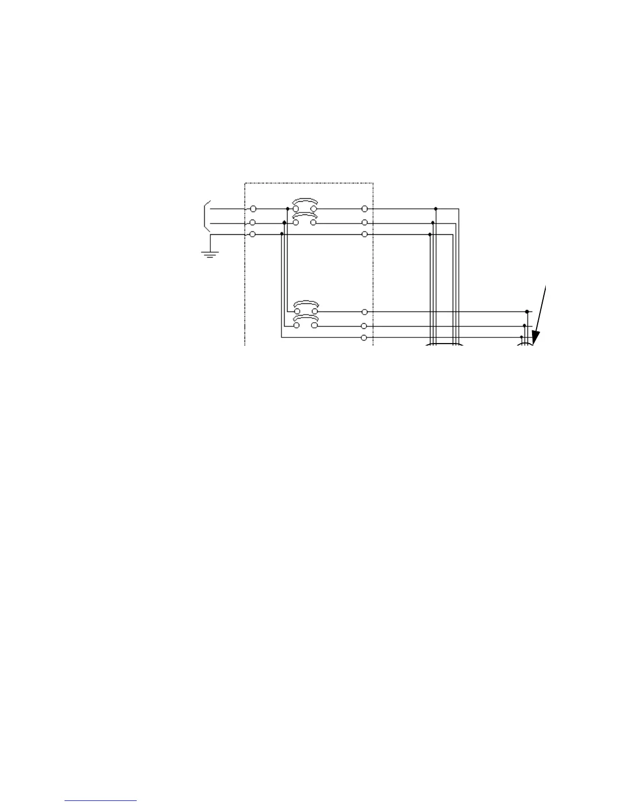
A standard, non-redundant power feeding diagram with 100V ac input is shown
Figure 5-3. Figure 5-4 shows its redundant power feeding counterpart, in which c
GR2000-2S is not applicable.
CB
100 Vac,
single phase,
50/60 Hz
Ground
NEMA 5-15
(convenienc
outlet)
 Loading...