GR2000 Installation Guide
3-16 GR2K-GA-1002
Rev. 6.03
3.4 Routing Processor (RP)
Three types of RP models, RP-A1 (standard), and RP-C/C6 and RP-D/D6 (options for
highspeed media), apply to the GR2000 device models as listed in Table 3-12. Each
RP model comprises one RP board. Description of each RP board follows.
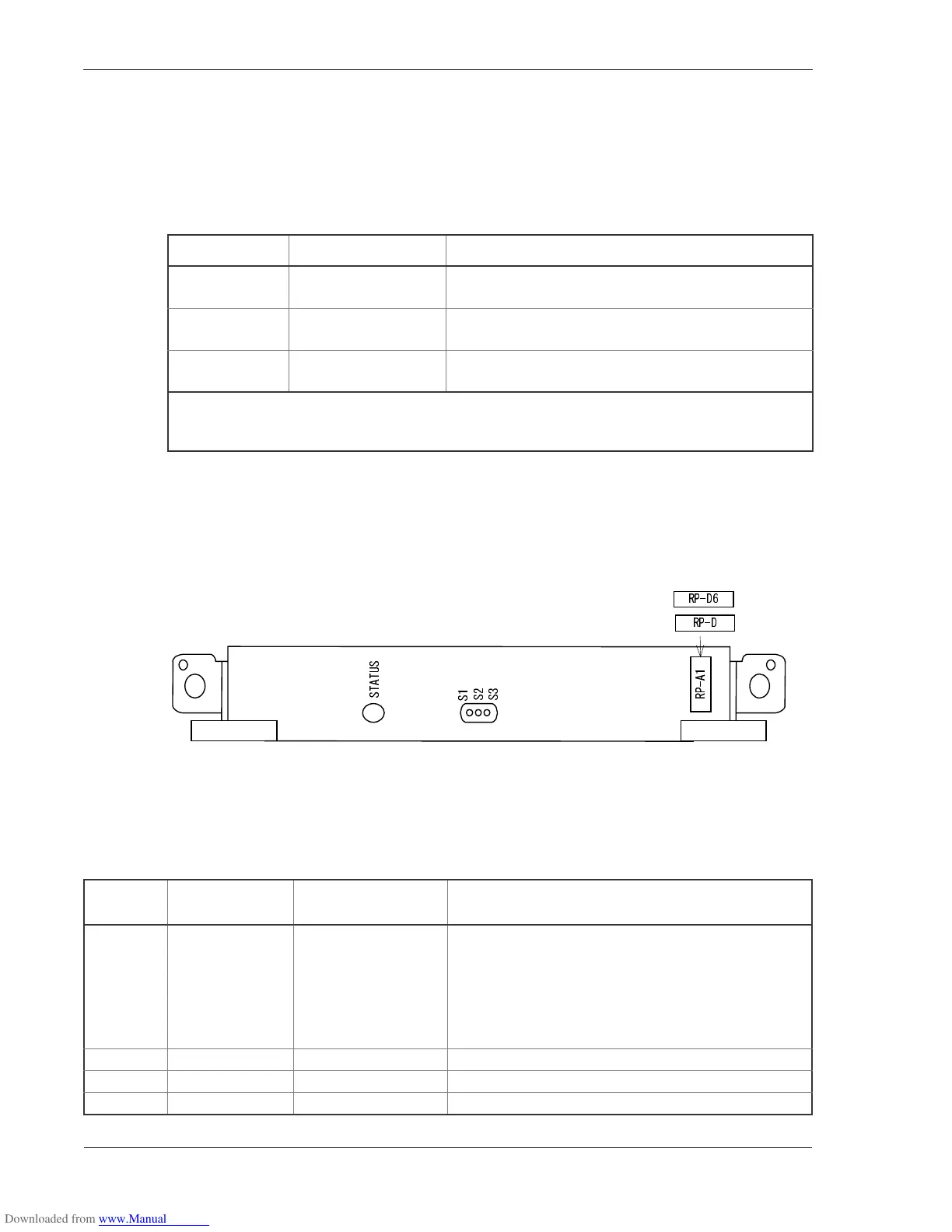
3.4.1 RP-A1/RP-D/RP-D6
TheRP-A1physicallyappearsasFigure3-20.ToexploretheswitchandLEDdisplay
functions, see the Operations Guide.
Figure 3-20 RP-A1/RP-D/RP-D6 Front Panel View
Switch and LED indication
Table 3-12 RP Models
RP Model Name Board Size Applicable Device Model
RP-A1 Full-size, 30mm-wide GR2000-4S, GR2000-6H, GR2000-10H, GR2000-20H,
GR2000-4, GR2000-10, and GR2000-20
RP-C/C6 Full-size, 30mm-wide GR2000-6H, GR2000-10*, GR2000-10H*, GR2000-20H*,
and GR2000-20*
RP-D/D6 Full-size, 30mm-wide GR2000-4S** GR2000-6H, GR2000-10, GR2000-10H,
GR2000-20H, and GR2000-20
* Use of RP-C sometimes limits configuration of these models. For details, see Section 4.2,
“Configuration Limits.”
** The MPLS or MPLS-based IP-VPN feature is not available for use with the GR2000-4S.
Table 3-13 BCU switch and function of LED indications
Nam
Name of switch
and LED
Status Content
STATUS LED: Green/
Yellow/ Red
Shows the operating
condition of RP.
Green: Operable operation
Yellow: Blocking and cock insertion and removal
possible.
Green blinking: Under preparation (being started up.)
Red: Fault
Extinguished: Operation not possible (Including the
device power supply being turned off)
S1 LED: Green Don’tcare
S2 LED: Green Don’tcare
S3 LED: Green Don’tcare
or
 Loading...