Component Details
GR2K-GA-1002 3-23
Rev. 6.03
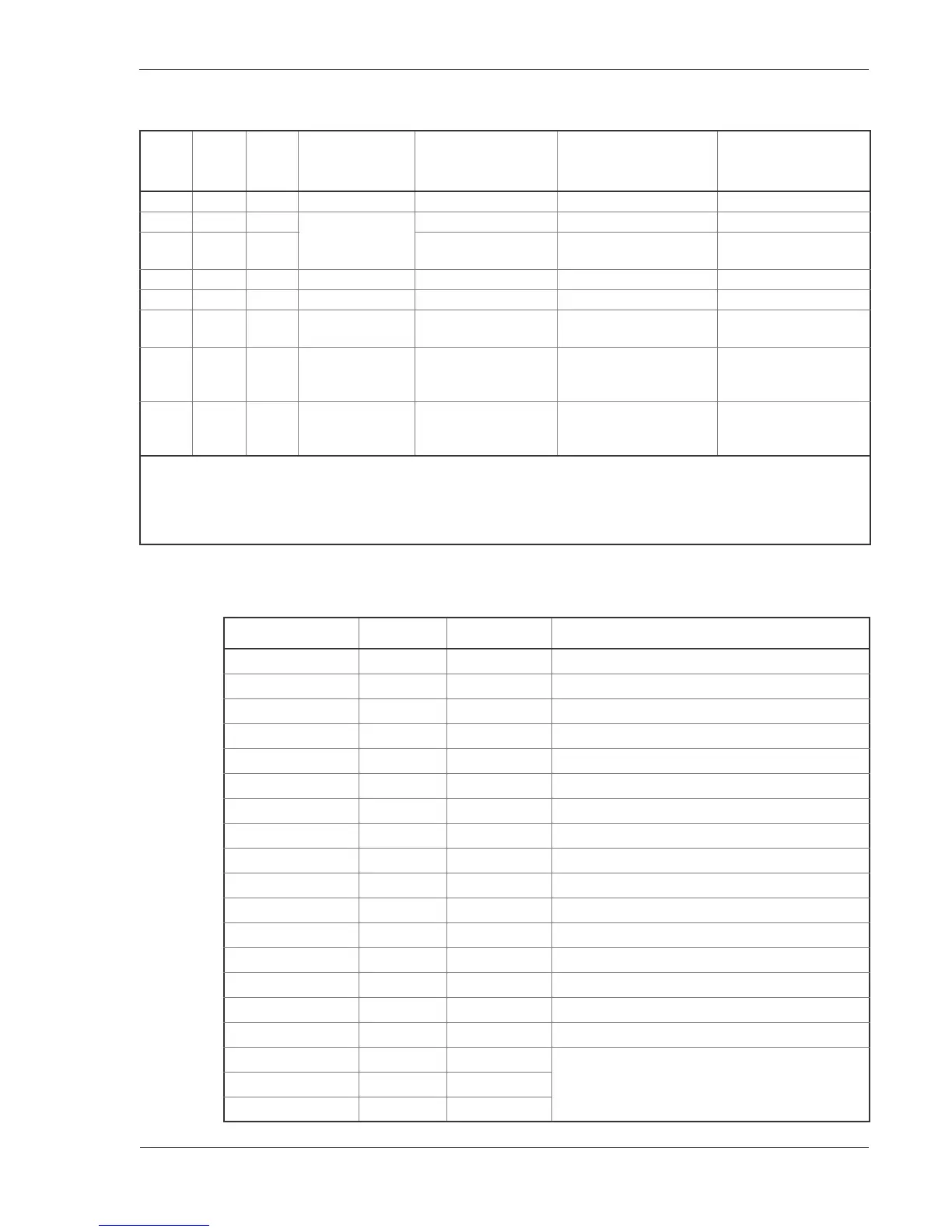
Table 3-22 NWVX-4 LINE LED indication
Act
(*1)
LINE
ERR
(*1)
T/R
(*1)
Line state Detail of state
State as seen by
SXMP
Line state indication
in MMI and browser
-- -- (*3) Being initialized. Being initialized (3). initialize
G -- (*3) Being operated In normal operation. In standby (3). active up
-- Y (*3) Line fault being
occurred.
In operation (line fault
being occurred (8).
active down
G -- (*3) Line test. Line being tested (9). test
-- -- -- In fault. In fault (4). fault
-- -- -- Command being
blocked.
In maintenance (7). closed
-- -- -- Not used. Configuration
definition not set yet
Not used.
Configuration definition
not set yet. (10)
unused
-- -- -- Configuration
definitions not
agreed.
Configurationdefinitions
not agreed. (11)
mismatch
(*1): G: Lights in green, Y: Lights in yellow, -: Goes off
(*2): Meaning and value of SMNP private MIB and gr2kPhysLineOperStatus
(*3): The T/R LED lights and goes off by H/W. In lighting conditions, this LED lights in green when the logical value of
send and receive data is "0". The LED lights in green when lighting conditions are detected irrespective of the line
state.
Table 3-23 Connector Specifications for NWVX-4, Pin Assignment for V.24
WAN 25-pin (Male) Connection Router 50-pin Specifications
2 ————— 9 SD (send data) (output)
3 ————— 10 RD (receive data) (input)
4 ————— 15 RS (request to send) (output)
5 ————— 16 CS (clear to send) (input)
6 ————— 12 DR (date set ready) (input)
7 ————— 34 SG (signal ground)
8 ————— 30 CD (carrier detect of data channel receive) (input)
15 ————— 22 ST2 (send element timing 2) (input)
17 ————— 32 RT (receive element timing) (input)
18 ————— 13 LLB (output)
20 ————— 11 ER (data terminal ready) (output)
21 ————— 23 RLB (output)
22 ————— 24 Ci (call indicator) (input)
24 ————— 31 ST1 (send element timing 1) (output)
25 ————— 14 Ti (test indicator) (input)
1 ————— shell FG (frame ground)
43 -44 Connection is required if the router is DTE.
Separate contact is required if it is DCE.
45 -46
5-6
 Loading...