Product Overview
GR2K-GA-1002 2-25
Rev 6.03
For the device configuration when PS is mounted with a DC input unit, and the
PS mounting position, please refer to the "Hardware operation manual".
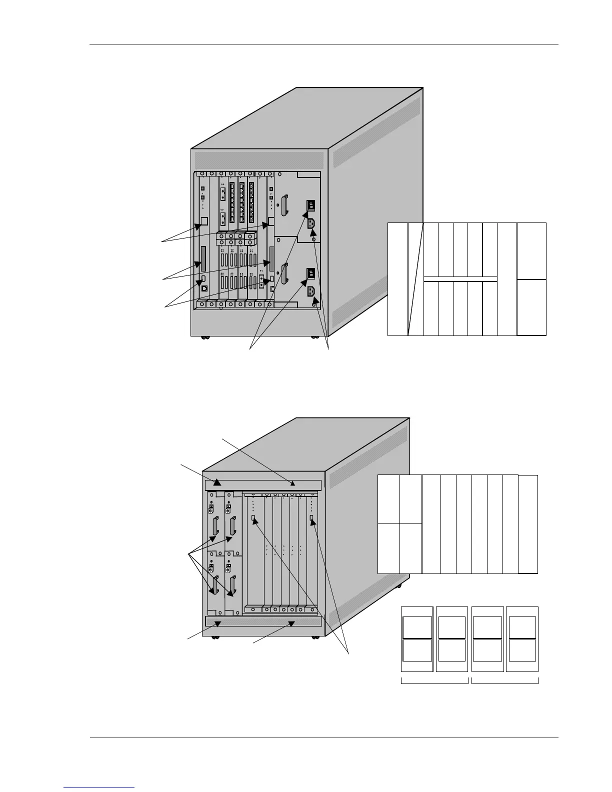
Figure 2-35 Front View of GR2000-10H with AC Input
Figure 2-36 Rear View of GR2000-10H with AC Input
3
0
88 88
NIF
5
NIF
4
NIF
6
NIF
7
NIF
8
NIF
9
RM-
IO1
NIF
0
NIF
1
NIF
2
NIF
3
LED (status
indicator)
Slot for the RM-10 NIF board
AC input unit mounting
position.
RS-232C
connector
(for console)
Memory
card slot
Power breaker (100V) or switch (200V)
Power cord receptacle
RM-
IO0
PS
INPUT1
(AC)
PS
INPUT0
(AC)
Mounting position of RM-CPU, RP
board power supply unit:
RP
4
RP
3
RP
2
RP
0
RP
1
RM-
CPU
0
RM-
CPU
1
DC-DC
1
DC-DC
0
DC-DC
3
DC-DC
2
RS-232C
connector
(for AUX)
FAN3
FAN1
FAN2
FAN0
Placement of fans in fan tray (top view):
Fan 4
(main)
Fan 2
(power)
Fan 3
(main)
Fan 1
(power)
(front)
(rear)
Upper fan tray
(front)
(rear)
FAN1
FAN3
Fan 4
(main)
Fan 2
(power)
Fan 3
(main)
Fan 1
(power)
(front)
(rear)
Lower fan tray
(front)
(rear)
FAN0
FAN2
DC-DC
Power
supply unit
 Loading...