- 16 -
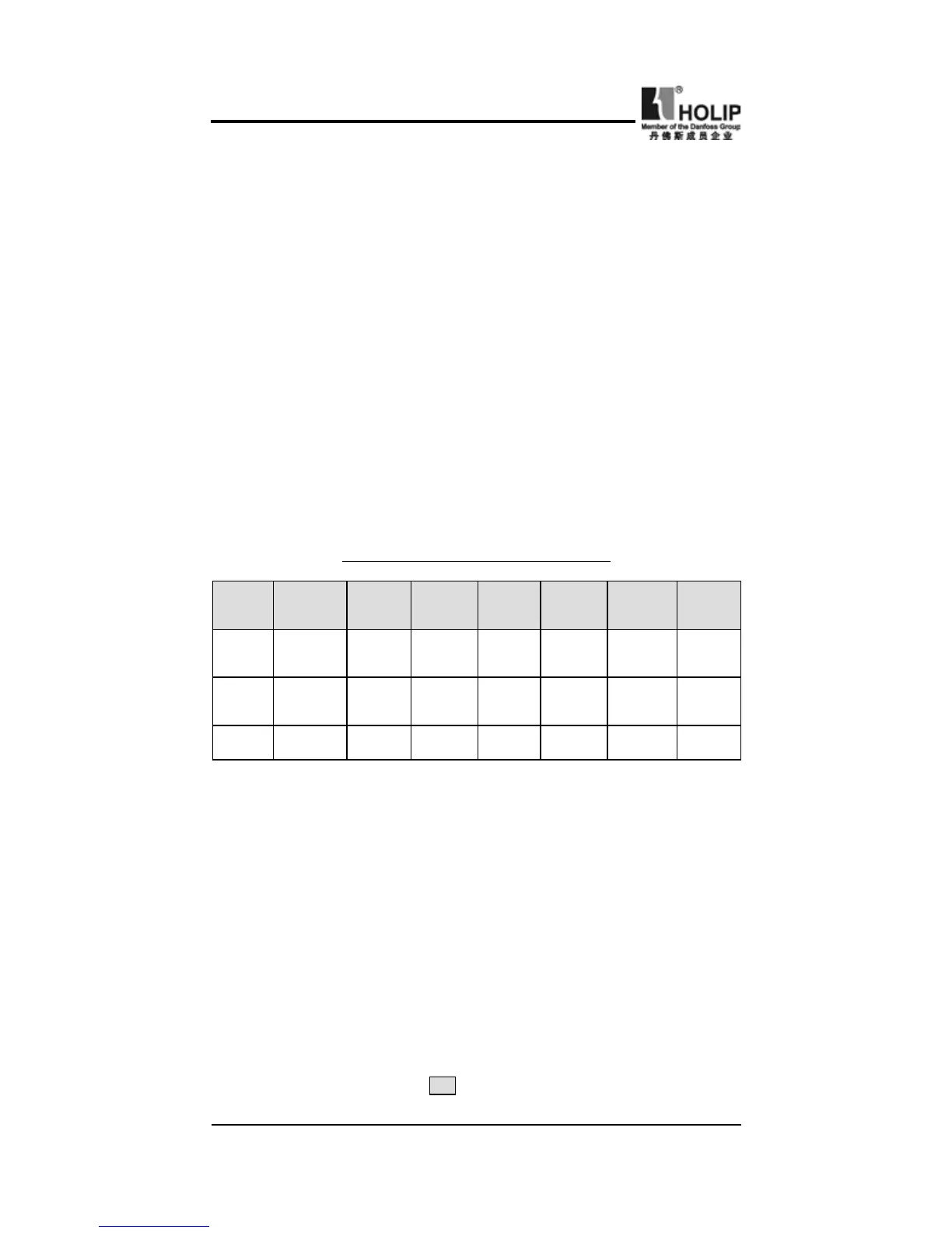
HLP-C
+
Inverters
Model
HLPC
+
00
D423B
HLPC
+
0
D7523B
HLPC
+
0
1D523B
HLPC
+
0
2D223B
HLPC
+
0
D7543B
HLPC
+
0
1D543B
HLPC
+
0
2D243B
NFB
Capacity
16A 16A 32A 32A 16A 16A 16A
Wire
Size
2.5mm² 2.5mm² 2.5mm² 4mm² 2.5mm² 2.5mm² 2.5mm²
Screw M4 M4 M4 M4 M4 M4 M4
Note: The parameters above are only for reference, not a standard.
be connected between the motor and the output terminals
(U.V.W) of the inverter.
● The main circuit wire must be enough far away from other
control equipments.
● When the wiring between the inverter and the motor exceeds
15 meters for 230V class or 30 meters for 440V class, much
higher dV/dT will be produced inside the coil of motor, which
will cause the destroy to the interlayor insulation of motor.
Please change it to a special AC motor for the inverter or add a
reactor on the side of the inverter.
● Please lower the carrier frequency if there is longer distance
betweent the inerter and the motor. Because the higher carrier
frequency will result in the bigger leakage current of high-
order harmonics of the cables the leakage current will have
unfavorable effect on the inverter and other equipment.
Specications for NFB and Wire
b
:
For control circuit wiring (signal line)
● The signal line should be separately laid in a different duct
with the main circuit wire to avoid any possible interference.
● Please use the shielded cable with the size of 0.5-2mm2 for
signal lines and make one end grounding. while the shielded
cable with the size of 1 mm² is recommended for the control
line.
● Use the control terminals correctly according to your needs.
c
:
Grounding
● Grounding terminal : The third grounding method
E