- 69 -
HLP-C
+
Inverters
from temperature, or pressure transmitter, etc. When under
PID control, the feedback signal input path is the analog current
signal 4-20mA.
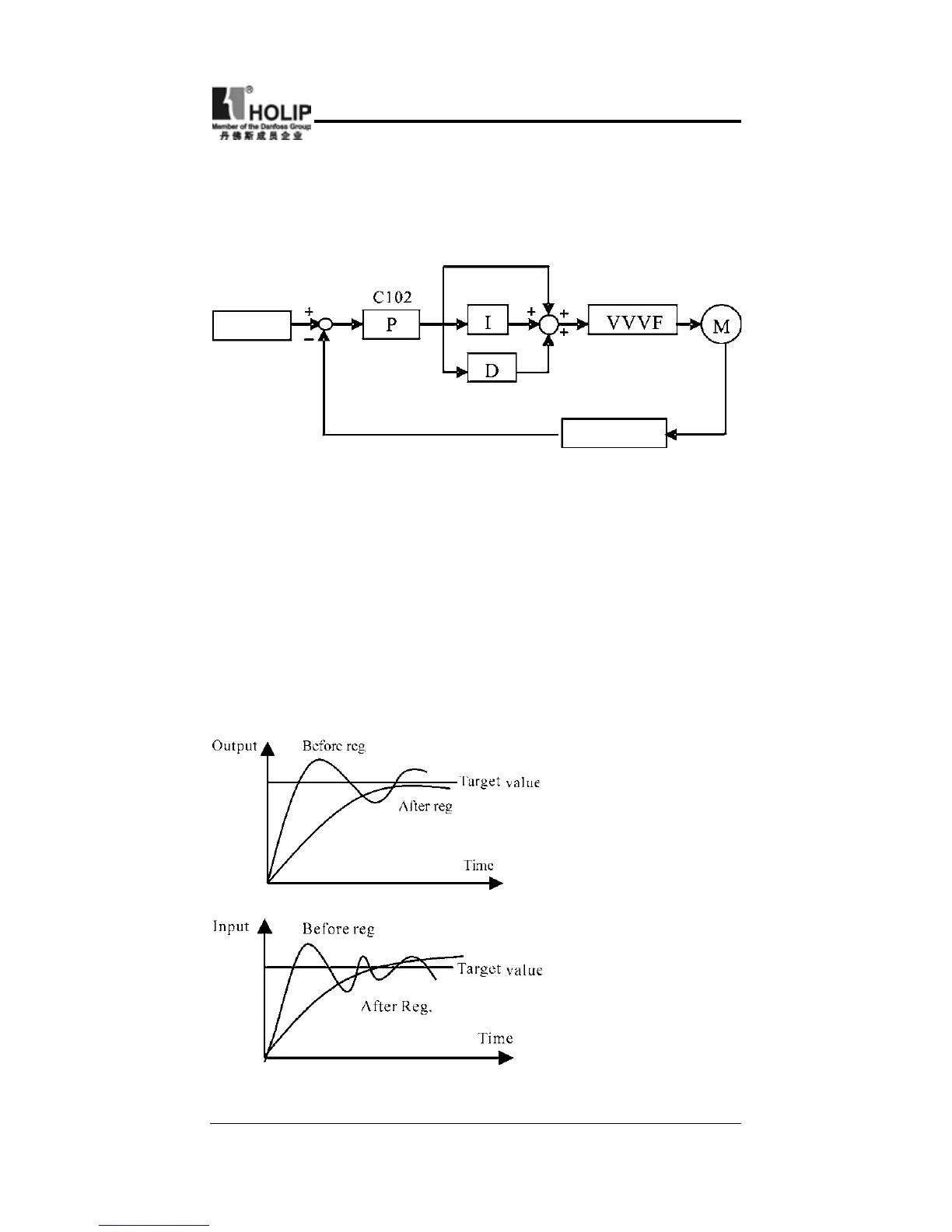
PID Control Block Diagram:
Target value
Feedback
Transmitter
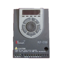
General operating methods of PID control:
⑴
Choose the correct transmitter (with the output specication
of standard current signal 4-20mA)
⑵
Set the right target value.
⑶
If t he out put doe sn’t have oscil lat ion, i nc rease t he
proportional constant (P);
⑷
If the output doesn’t have oscillation, decrease the integral
time (Ti);
⑸
If the output doesn’t have oscillation, increase the differential
time (Td).
1
.
Decrease the Over
Output
a
:
Decrease the
differential time (D)
b
:
Increase the
integral time (I)
2
.
Decrease the
oscillation
a
:
Decrease the
differential time (D)
b
:
Extend the integral
timke
(
P
)