2-74
[11]
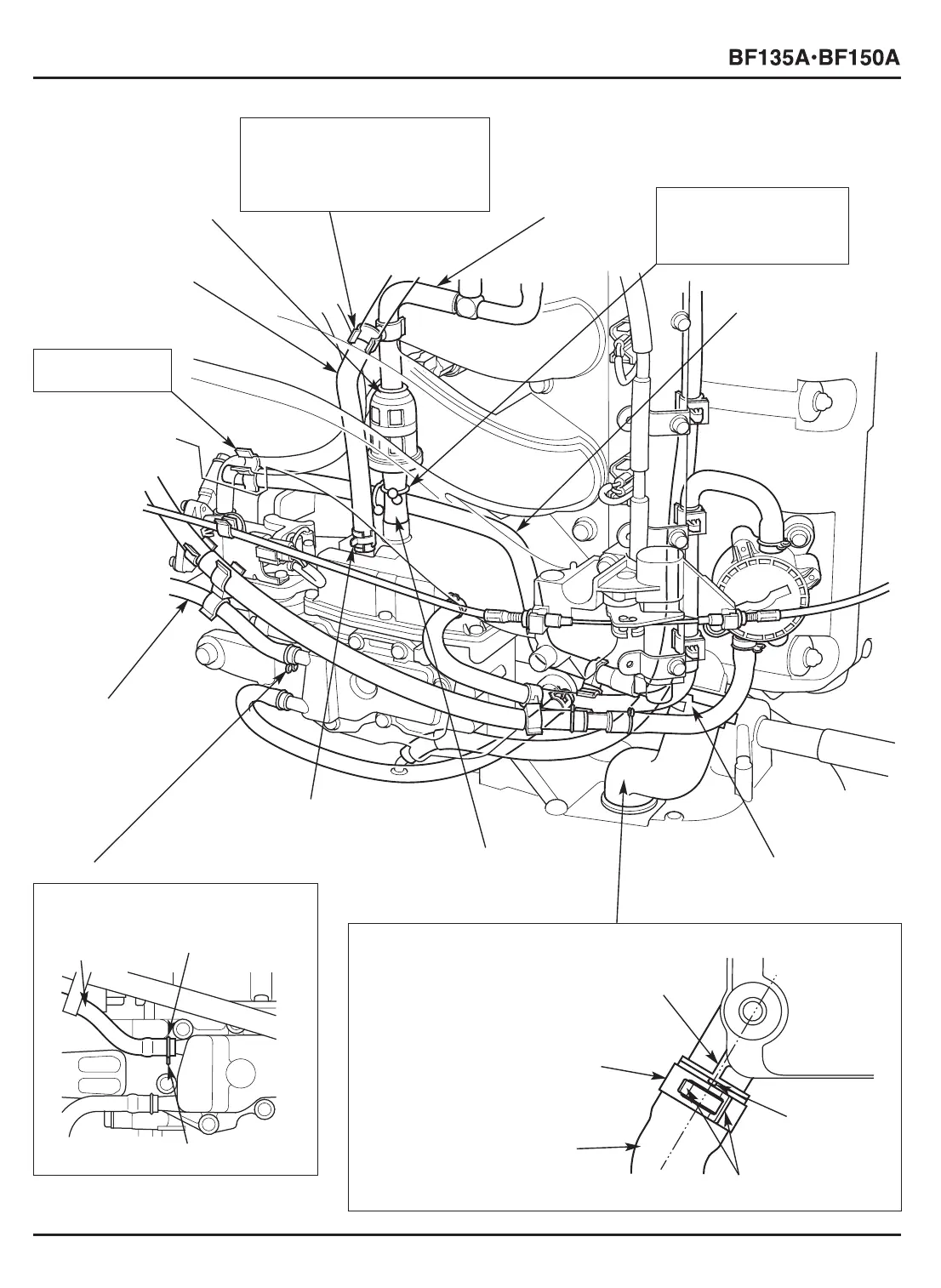
TUBE CLAMP
D10.7
[10]
AIR VENT TUBE E
[5]
AIR VENT
TUBE B
[2]
PRESSURE REGULATOR
RETURN HOSE
[4] HOSE CLAMP
Set the air vent tube B in the
clamp of the larger diameter
side and the pressure regulator
return hose in the smaller
diameter side.
[9] OIL TUBE
• Install the oil tube aligning the
projection on the oil tube
installation part with the
projection of the oil tube.
• Install the tube clamp D32.5
with the lugs in the position
shown.
[3] VAPOR
CHAMBER
[9]-3 OIL TUBE
[9]-1
PROJECTION
[9]-1
PROJECTION
[9]-4 TUBE CLAMP D32.5
[8] TUBE CLAMP D32.5
[9]-2 LUGS
[12] TUBE CLIP
Install with the lugs facing down.
[12]-2 TUBE CLIP
[12]-3 LUGS
[6] TUBE CLIP
Clamp the air vent tube
E and the fuel hose
(high pressure side) as
shown.
[1] HOSE CLAMP
INSTALLATION:
P. 2-61
[7]
FUEL HOSE (HIGH
PRESSURE SIDE)
[13]
7 x 400 mm TUBE
[12]-1
7 x 400 mm
TUBE
 Loading...