2. Specifications
2.4. Functions
44 Analog Input Module 2MLF-AV8A, AC8A User's Guide R200
Honeywell September 2010
Function to detect input signal failure/disconnect
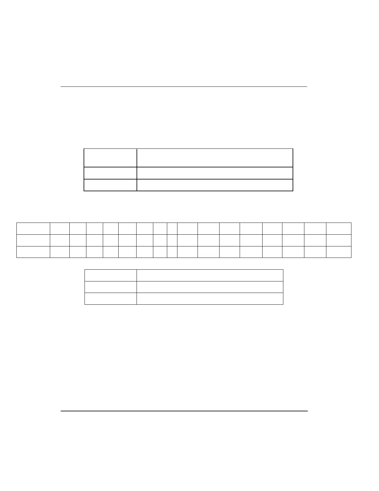
1. Input Range
This detection function is available only if the input signal range is 1 ~ 5V or 4 ~ 20mA.
Detection conditions for respective input signal ranges are as described in the below
table.
Input signal
range
Voltage/Current value regarded as disconnected
1 ~ 5V 0.2V or less
4 ~ 20mA 0.8mA or less
2. Disconnection display for respective channels
Detection status bit of signal failure/disconnect for respective input channels is saved
on UXY. 10. (X denotes Base No., and Y denotes Slot No.)
Bit 15 14 13 12 11 10 9 8
7 6 5 4 3 2 1 0
Default 0 0 0 0 0 0 0 0
0 0 0 0 0 0 0 0
Assigned - - - - - - - - CH7 CH6 CH5 CH4 CH3 CH2 CH1 CH0
BIT Description
0 Normal
1 Disconnected
3. Operation
Each bit is set to 1 if an assigned channel is detected as disconnected, and is set back
to 0 when the channel is connected back again. In addition, each bit can be used to
detect the disconnection in the user program together with execution conditions.
4. Program example
A program example of analog input module installed on Base No. 0 and Slot No. 2
detecting a input signal failure/disconnect and storing the respective channel number
on the P area.
(System configuration)
 Loading...


