5. Configuration and Function of Internal Memory
5.2. I/O area of A/D converted data
74 Analog Input Module 2MLF-AV8A, AC8A User's Guide R200
Honeywell September 2010
Address Details
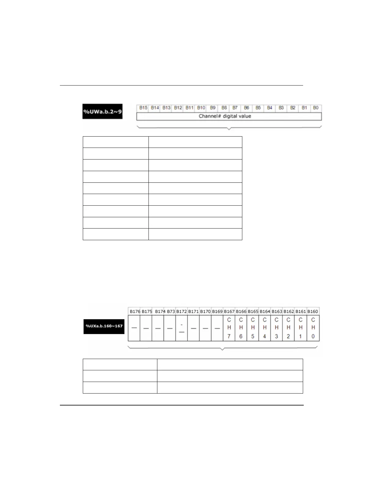
%UWa.b.2 CH0 digital value
%UWa.b.3 CH1 digital value
%UWa.b.4 CH2 digital value
%UWa.b.5 CH3 digital value
%UWa.b.6 CH4 digital value
%UWa.b.7 CH5 digital value
%UWa.b.8 CH6 digital value
%UWa.b.9 CH7 digital value
Detect input signal failure/disconnect flag (%UXa.b.160~167 a: Base No., b: Slot
No.)
Failure/disconnect status bit for respective input channels is saved in %UXa.b.
Each bit is set to 1 if an assigned channel is detected as disconnected, and it is reset to 0
if connected back. In addition, this bit can be used in the program, together with
execution conditions.
BIT Description
0 Normal
1 Disconnection

 Loading...


