5. Configuration and Function of Internal Memory
5.3. Operation parameters settings area
76 Analog Input Module 2MLF-AV8A, AC8A User's Guide R200
Honeywell September 2010
5.3 Operation parameters settings area
One word (2 bytes) is assigned for each address in the internal memory, which can be
displayed in 16 bits. Each of the 16 bits can be set: On – ‘1’ or Off – ‘0’ for various
functions.
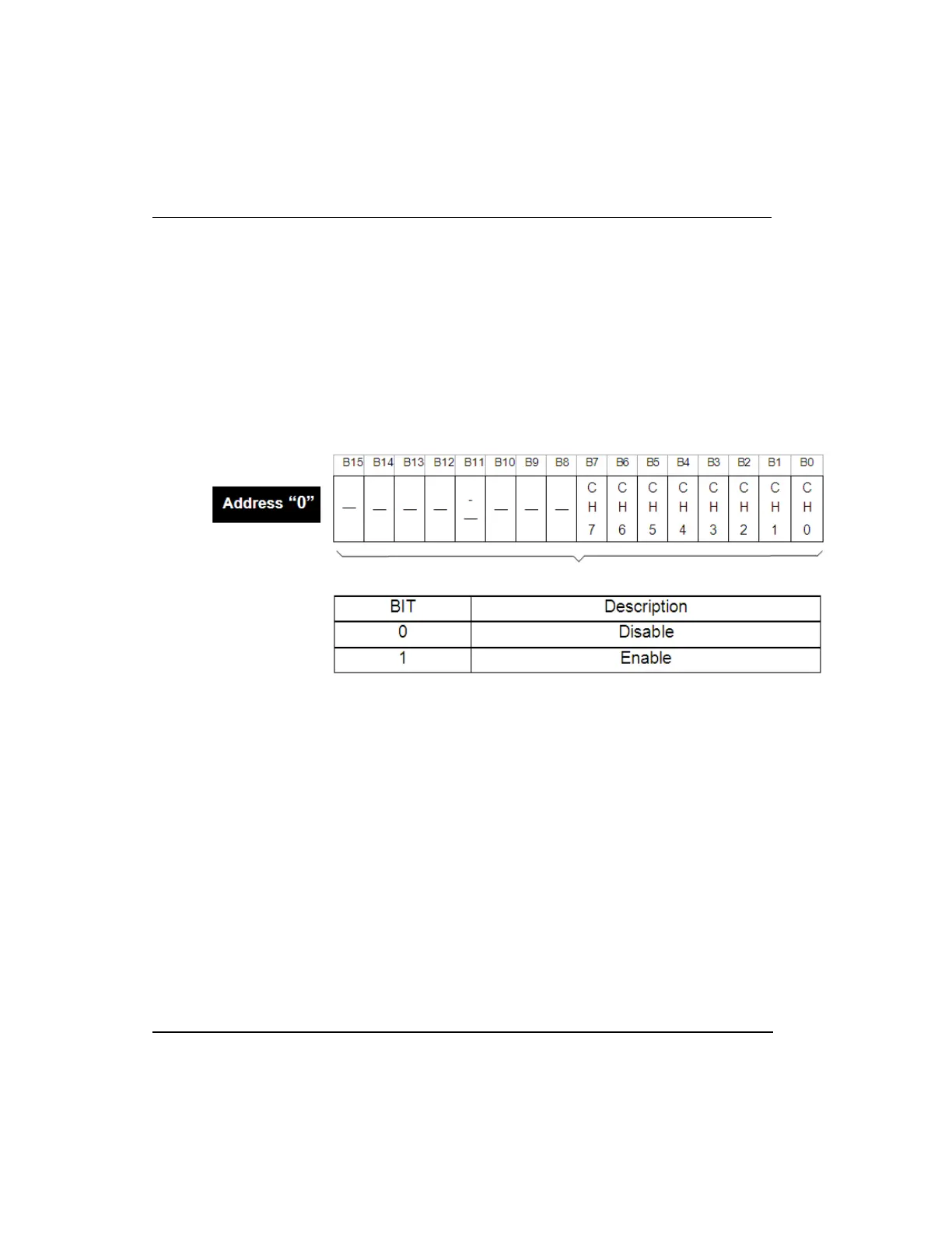
Address 0 - A/D conversion enable/disable status for each channel
Enable/disable status of A/D conversion for each channel can be set as below:
1. Set all unused channels as ‘Disable’. This saves the conversion cycle time.
2. B8 ~ B15 bits are reserved for future use.
Address 1 - Input voltage/current range
1. The range of analog input voltage/current is specified for each channel.
2. If the analog input range is not specified, the range of all the channels is set to 1 ~
5V (or 4 ~ 20mA).
3. Setting range of analog input voltage/current is as explained below.

 Loading...


