5. Configuration and Function of Internal Memory
5.5. PUT/GET function block use area (parameter area)
R200 Analog Input Module 2MLF-AV8A, AC8A User's Guide 97
September 2010 Honeywell
Output data range setting
1. Digital output data range for analog input can be set per channel.
2. When output data range is not set, all channels are set as 0~16000.
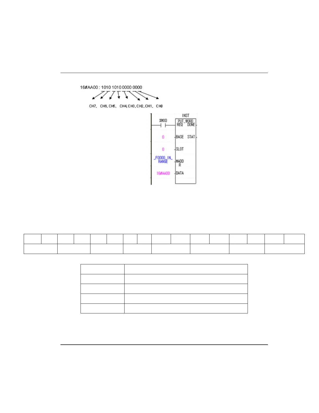
3. The following figure is an example for setting CH0~CH3 as -8000~8000,
CH4~CH7 as 0~10000.
B15 B14 B13 B12 B11 B10 B9 B8 B7 B6 B5 B4 B3 B2 B1 B0
CH7 CH6 CH5 CH4 CH3 CH2 CH1 CH0
BIT Description
00 Unsigned value:0 ~ 16000
01 Signed value:-8000 ~ 8000
10 Precise value
11 Percentile value:0 ~ 10000
 Loading...


