5. Configuration and Function of Internal Memory
5.2. I/O area of A/D converted data
R200 Analog Input Module 2MLF-AV8A, AC8A User's Guide 73
September 2010 Honeywell
5.2 I/O area of A/D converted data
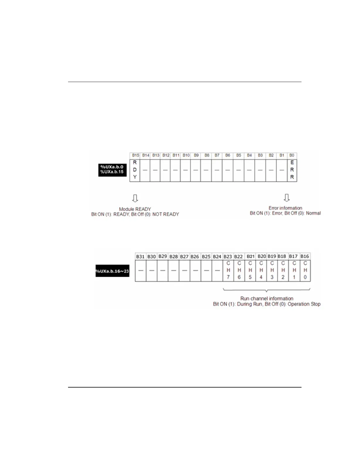
Module Ready/Error (%UXa.b.0, %UXa.b.15; a: Base No., b: Slot No.)
%UXa.b.15: It is ON when PLC CPU is powered or reset with A/D conversion, ready to
process A/D conversion.
%UXa.b.0: It is a flag to display the error status of A/D conversion module.
Run channel (%UXa.b.16~23, a: Base No., b: Slot No.)
This area stores Enable/Disable (Run/Stop) information of individual channel.
Digital output value (%UWa.b.2 ~9, a: Base No., b: Slot No.)
A/D conversion value is output to buffer memory addresses 2 ~ 9 (%UWa.b.2 ~9) for
respective channels.
Digital output value is saved in 16-bit binary.

 Loading...


