R200 Analog Input Module 2MLF-AV8A, AC8A User's Guide 69
September 2010 Honeywell
5. Configuration and Function of Internal Memory
5.1 Internal memory configuration
A/D conversion module has its own internal memory to transmit/receive data to/from
PLC CPU.
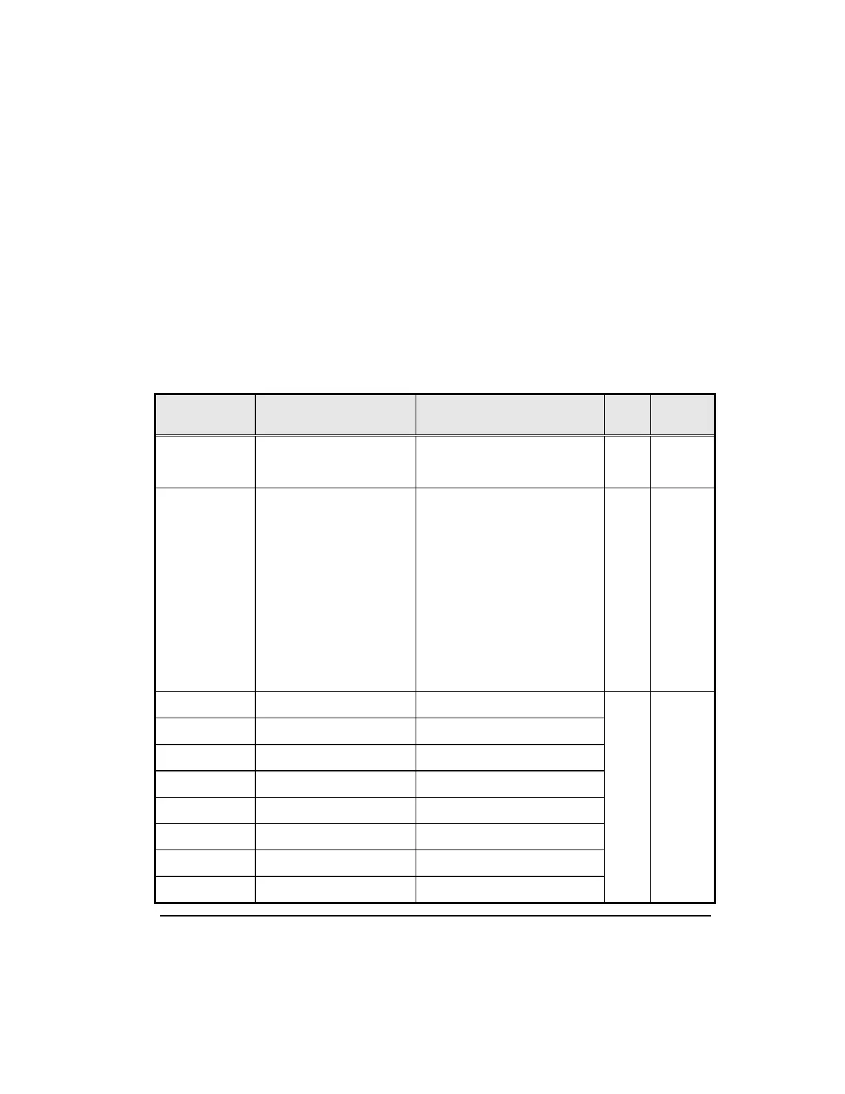
The following table lists the details of the I/O area of A/D converted data..
Table 5 – I/O area of A/D converted data
Address
Assigned
Global Variable
Details R/W
Directio
n
%UXa.b.0
%UXa.b.15
_ab_ERR
_ab_RDY
Module ERROR
Module READY
R
A/D →
CPU
%UXa.b.16
%UXa.b.17
%UXa.b.18
%UXa.b.19
%UXa.b.20
%UXa.b.21
%UXa.b.22
%UXa.b.23
_ab_CH0_ACT
_ab_CH1_ACT
_ab_CH2_ACT
_ab_CH3_ACT
_ab_CH4_ACT
_ab_CH5_ACT
_ab_CH6_ACT
_ab_CH7_ACT
CH0 Active
CH1 Active
CH2 Active
CH3 Active
CH4 Active
CH5 Active
CH6 Active
CH7 Active
R
A/D →
CPU
%UWa.b.2 _ab_CH0_DATA CH0 Output
R
A/D →
CPU
%UWa.b.3 _ab_CH1_DATA CH1 Output
%UWa.b.4 _ab_CH2_DATA CH2 Output
%UWa.b.5 _ab_CH3_DATA CH3 Output
%UWa.b.6 _ab_CH4_DATA CH4 Output
%UWa.b.7 _ab_CH5_DATA CH5 Output
%UWa.b.8 _ab_CH6_DATA CH6 Output
%UWa.b.9 _ab_CH7_DATA CH7 Output

 Loading...


