5. Configuration and Function of Internal Memory
5.1. Internal memory configuration
70 Analog Input Module 2MLF-AV8A, AC8A User's Guide R200
Honeywell September 2010
Address
Assigned
Global Variable
Details R/W
Directio
n
%UXa.b.160
%UXa.b.161
%UXa.b.162
%UXa.b.163
%UXa.b.164
%UXa.b.165
%UXa.b.166
%UXa.b.167
_ab_CH0_IDD
_ab_CH1_IDD
_ab_CH2_IDD
_ab_CH3_IDD
_ab_CH4_IDD
_ab_CH5_IDD
_ab_CH6_IDD
_ab_CH7_IDD
CH0 Input Disconnection
CH1 Input Disconnection
CH2 Input Disconnection
CH3 Input Disconnection
CH4 Input Disconnection
CH5 Input Disconnection
CH6 Input Disconnection
CH7 Input Disconnection
R
A/D →
CPU
%UXa.b.176
_ab_ERR_CLR
Error clear request W
CPU →
A/D
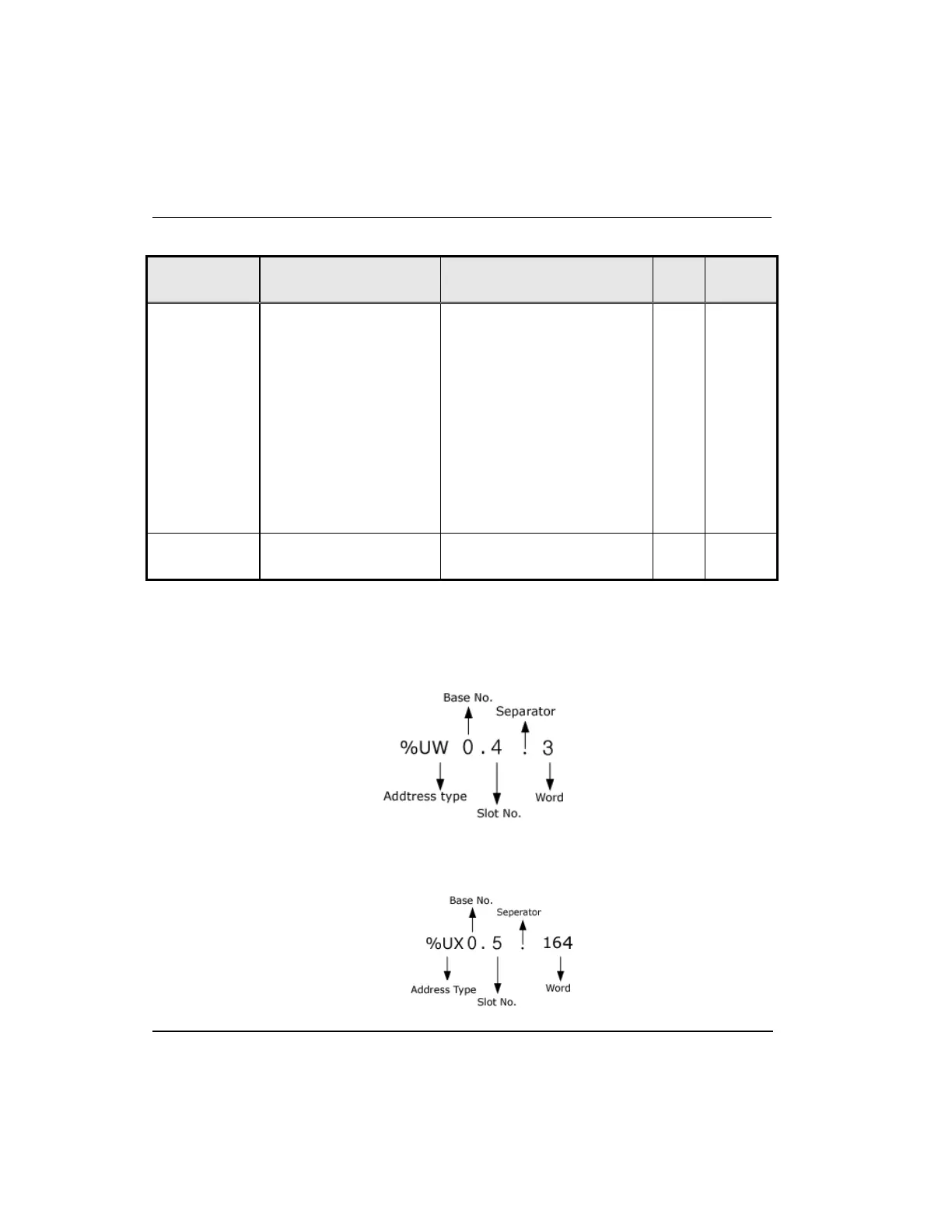
In the address assigned, ‘a’ denotes the Base No. and ‘b’ denotes the Slot No. on which
the module is installed.
In order to read ‘CH1 digital value’ of A/D conversion module installed on Base No. 0,
Slot No. 4, it is displayed as %UW0.4.3.
In order to read ‘CH4 Input disconnection’ of A/D conversion module installed on Base
No. 0, Slot No. 5, it is displayed as %UX0.5.164.

 Loading...


