3. Installation and wiring
3.2. Wiring
R200 Analog Input Module 2MLF-AV8A, AC8A User's Guide 51
September 2010 Honeywell
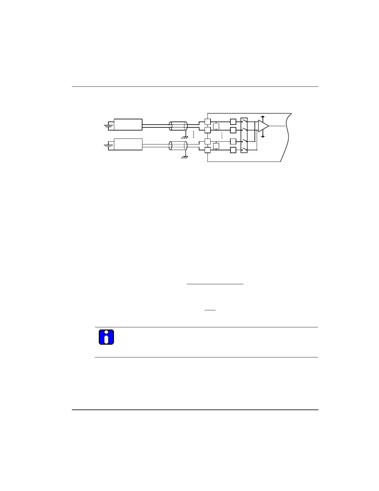
Wiring example of 4- wire sensor/transmitter (voltage/current input)
+
R
4-Wire ???
4-Wire ???
-
CH0
CH7
+
-
R
R
R
DC
+
-
DC
+
-
*3
R
R
*2
*2 *3
*1
*1
Relationship between voltage input accuracy and wiring length
With voltage input, the wiring (cable) length between transmitter/sensor and module has
an effect on digitally-converted values of the module as specified below:
where,
Rc: Resistance value due to line resistance of cable
Rs: Internal resistance value of transmitter or sensor
Ri: Internal resistance value (1MΩ) of voltage input module
Vin: Voltage allowed to analog input module
% Vi: Tolerance of converted value (%) due to source and cable length in voltage input
( )
[ ]
RiRcRs
Vin
+×+
=
2
%
ATTENTION
With current input, there is no accuracy, tolerance caused by cable length
and internal resistance of the source.
 Loading...


