5. Configuration and Function of Internal Memory
5.5. PUT/GET function block use area (parameter area)
R200 Analog Input Module 2MLF-AV8A, AC8A User's Guide 95
September 2010 Honeywell
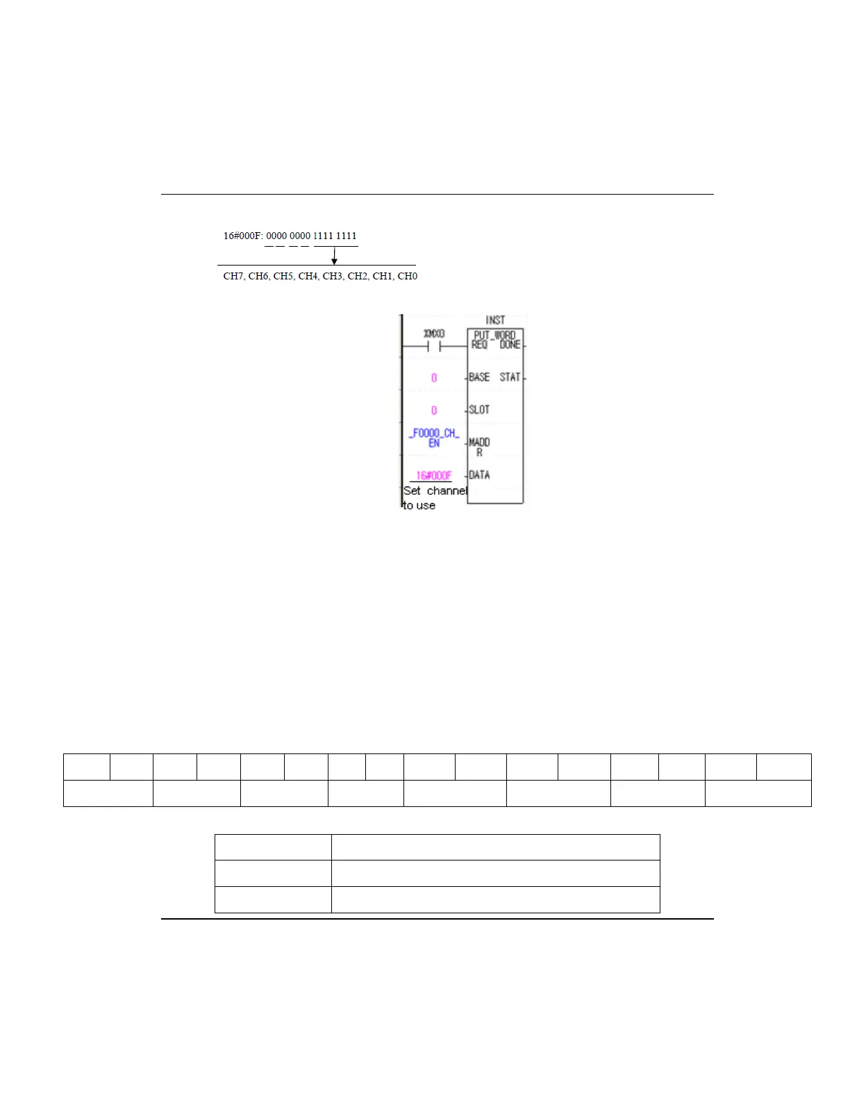
5. The value in B8~B15 is ignored.
6. The above figure is an example for enabling CH0~CH3 of A/D module equipped at
slot 0.
Input voltage/current range setting
1. You can set input voltage/current range per channel.
2. When analog input range is not set, all channels are set as 1 ~ 5V (4 ~ 20mA).
3. Setting of analog input voltage/current range is as follows.
− 2MLF-AV8A
The following is an example for setting CH0~CH3 as 1~5V and CH4~CH7 as 0~10V.
B15 B14 B13 B12 B11 B10 B9 B8 B7 B6 B5 B4 B3 B2 B1 B0
CH7 CH6 CH5 CH4 CH3 CH2 CH1 CH0
BIT Description
00 1V ~ 5V
01 0V ~ 5V

 Loading...


