Galaxy Dimension Installer Manual
6-21
Access Door MAX LED Status
When the access doors option is entered in engineering mode the MAX address can be displayed by pressing
the # key. This is shown in the following Figure graphically for a MAX address as 26.
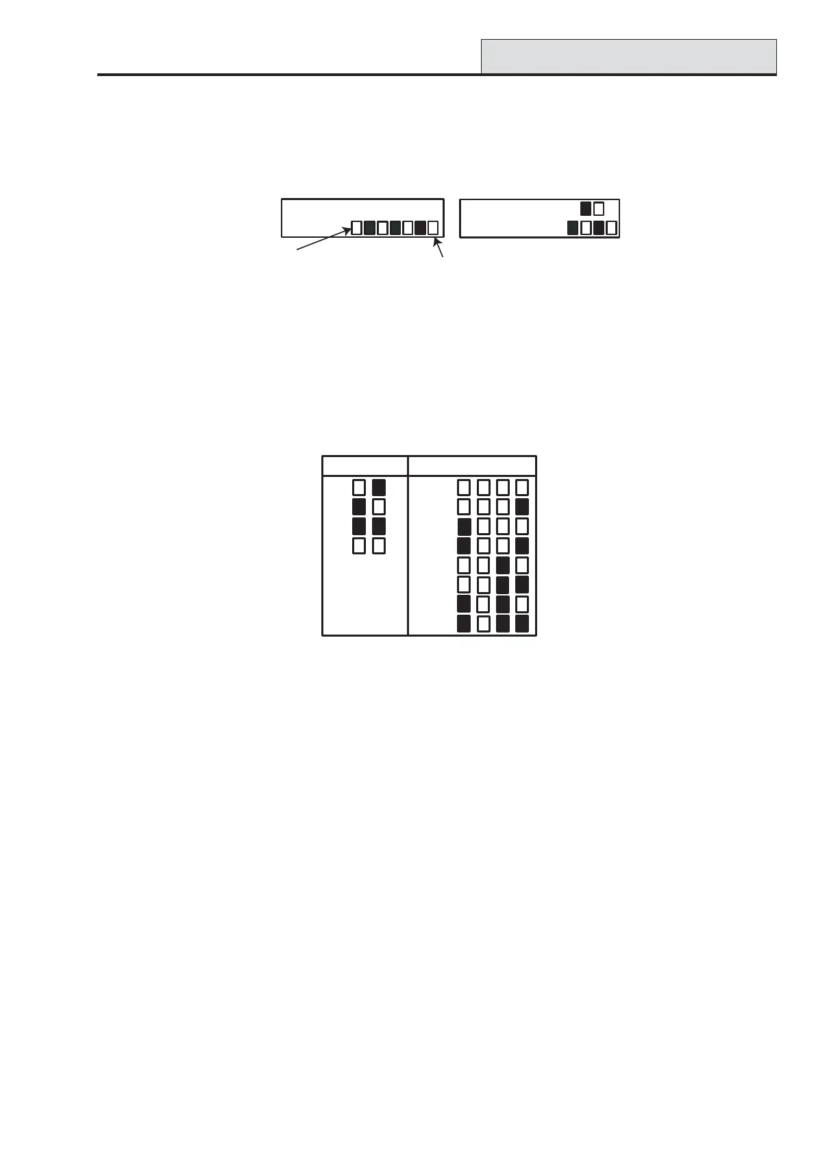
Figure 6-1. LED Status
The line numbers are represented by the top row in MAX and blocks 2
nd
and 3
rd
from the top in the
MicroMAX/MAX
3
and the address numbers are represented by the bottom row of blocks in the MAX and
the four bottom blocks in the MicroMAX/MAX
3
. The top LED on the MicroMAX or MAX
3
is always off in
this mode.
The combinations are shown in the following Figure:-
Figure 6-2. Line Number/Module Address
Address
The first digit of the two digit number refers to the line that the module is connected to ( Line 1 on the Galaxy
GD-48; lines 1-2 on Galaxy GD-96/264; and lines 1–4 on the Galaxy GD-520); the second digit is the
physical address number of the MAX module. For example, a MAX module displaying as 25 indicates that
the module is on line 2 and is addressed as 5.
Pressing the # key gives a graphic representation of the MAX address in a binary format. The top two boxes
on the top row indicate the line address; the bottom four boxes indicate the physical address.
Descriptor
The descriptor is a maximum of 16 characters entered in the MAX Parameters option (69.2.2) or DCM
Parameters (69.3.1).
Engineer Mode
On accessing the Access Doors option in engineering mode, each on-line MAX/DCM module displays its
address by lighting the appropriate LEDs. To help the engineer identify each of the MAX/DCM modules, the
keypad displays a graphic representation of the MAX/DCM module address. By matching the (LED off)
and (LED on) image to the LEDs on the MAX/DCM, the engineer can identify each MAX/DCM module
on the system.
25 - Access Doors (cont’d)
Line No.
Module Address
4
1
3
2
4
1
3
2
0
7
6
5
2 6M A X
2 6
MicroMAX/MAX3 LEDs Displayed
MAX LEDs Displayed
M A X
Top (unused)
Bottom

 Loading...


