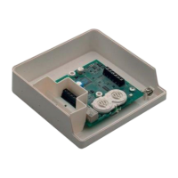
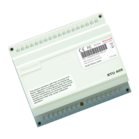
6TR80 - Installation and Operation Guide
1.3.3 Wiring Connections
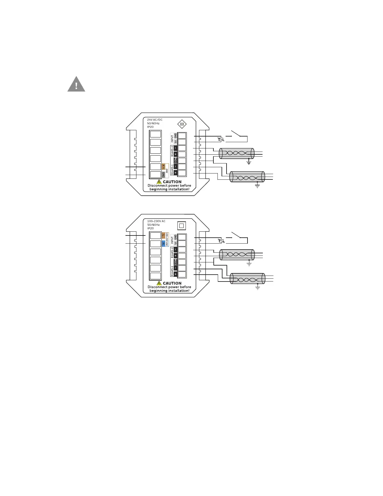
Wiring diagram for 24V AC/DC and 100 - 230V AC Power Supply are shown below.
(1)
Shield should be connected to earth ground at one end only.
Caution: Electrical Shock or Equipment Damage Hazard.
Can shock individuals or short equipment circuitry.
Disconnect power supply before Installation.
All wiring must comply with local electrical codes and ordinances or as
per below wiring connections.
100-230 V AC
24 V AC/DC
NTC / 0-10V / DI
RS485-1 (Controller)
RS485-2 (Dali 64)
(1)
(1)
1
2
3
4
5
6
13
12
11
10
9
8
7
(1)
(1)
1
2
3
4
5
6
13
12
11
10
9
8
7
NTC / 0-10V / DI
RS485-1 (Controller)
RS485-2 (Dali 64)

 Loading...