TR80 - Installation and Operation Guide36
3.4 GENERAL MONITORING REGISTERS
3. 4. 1 Fault Conditions
Device Faults register indicates several fault conditions that may exist on the device.
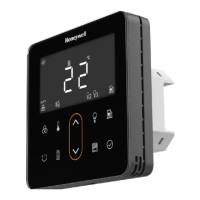
The same information is displayed on the screen with the same error numbers. For exam-
ple, a display of “E02” indicates an external sensor fault.
Port 1 comms fault is activated when no comms is received from master for 60 secs.
External sensor fault (bit2) is determined with comparison against the below valid ranges:
•NTC sensors: -10...+60 °C
•0-10V input: 0…11 V
•2-10V input: 1.5…11 V
3. 4. 2 Override Status and Reset
Register
type
Relative
Address
Absolute
Address
DirNameTypeRange
Default
value
Input330004RDevice Faultsbitwise
Bit 0: (reserved)
Bit 1: on-board sensor fault
Bit 2: external sensor fault
Bit 3: Port1 modbus loss of comms
Bit 4: Port2 receive timeout
Bit 5: Setpoint min/max mismatch
Bit 6: Fan Speed min/max mismatch
Bit 7: Lights min/max mismatch
Bit 8: Blinds min/max mismatch
0
Register
type
Relative
Address
Absolute
Address
DirNameTypeRange
Default
value
Input430005R
Override
status
bitwise
Bit0: Setpoint changed from the
default
Bit1: Fan speed is overridden (not
auto)
Bit2: HVAC mode overridden
Bit3: {reserved}
Bit4: Occupancy overridden
Bit5: DnD active
Bit6: MuR active
0
Holding100041001R/W
Override
reset
bitwise
Bit0: Reset Setpoint
Bit1: Reset Fan Speed to AUTO
Bit2: Clear HVAC mode override
Bit3: Clear Occupancy Override except
for holiday
Bit4: Clear Occupancy Override
include holiday
Bit5: Clear DnD
Bit6: Clear MuR
Bit7: Reset temperature unit to °C
Bit15: Restart wall module and clears
all user setting (Configuration setting
saved to flash memory remain
unchanged).
0
 Loading...