APPENDIX
A
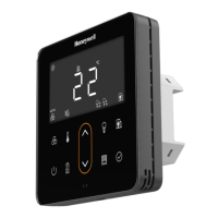
TR80 - Installation and Operation Guide60
TROUBLESHOOTING
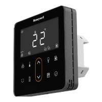
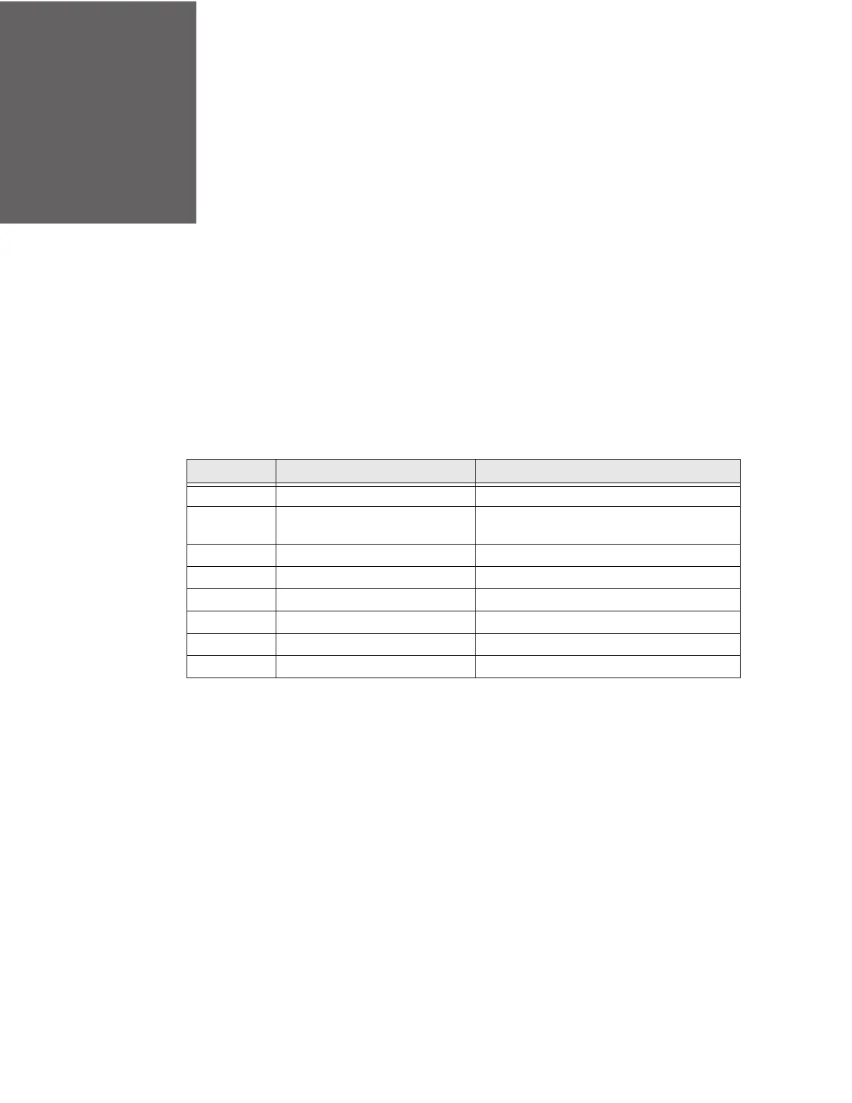
The fault condition is displayed on screen along with alarm symbol. Press OK but-
ton in ready mode then, up/down buttons to cycle the display between several val-
ues.
The fault condition will be displayed as an error code. Refer the troubleshooting
table listed below to understand the error codes, it’s meaning and action to be per-
formed to resolve the error.
Error Code Meaning Action
E01Onboard sensor fault Contact Customer care
E02External sensor faultCheck wiring and replace sensor if faulty
E03Modbus loss of commsCheck wiring and master controller
E04Port 2 timeout faultCheck wiring and DALI64 sensor on port 2
E05 Setpoint min/max mismatchContact customer care
E06Fan Speed min/max mismatchContact customer care
E07Lights min/max mismatchContact customer care
E08Blinds min/max mismatchContact customer care
 Loading...